Bently Nevada 330180-90-05 Dedicated Preamplifier for Eddy Current Monitoring Systems

Bently Nevada 330180-90-05 Dedicated Preamplifier for Eddy Current Monitoring Systems

Brand: Bently Nevada

Product ID: 330180-90-05

Condition: New / used

Terms of payment: Paypal、T/T 、Western Union

Category:

Description

1. Overview

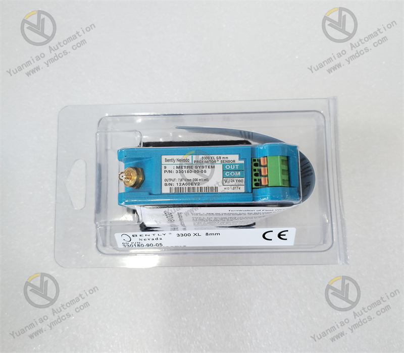
Bently Nevada 330180‑90‑05 is a dedicated Proximitor Sensor for the Baker Hughes Bently Nevada 3300 XL 8 mm eddy‑current proximity monitoring system. As the core signal conditioning and conversion unit of the complete eddy‑current transducer system, it is specially matched with 8 mm series eddy‑current probes and supporting extension cables. It is widely deployed in shaft condition‑monitoring and protection systems for key rotating machinery such as steam turbines, centrifugal compressors, large‑size fans, heavy‑duty pumps and electric motors in thermal‑power, chemical, oil‑gas and metallurgical industries.


This OEM‑standard 9‑meter‑system Proximitor fully complies with API 670 industrial monitoring standard. It receives weak high‑frequency induction signals from eddy‑current probes and performs signal filtering, amplification, shaping, linear compensation and temperature calibration. It converts non‑contact gap variations into standard linear DC voltage signals and transmits them to full‑range Bently Nevada monitor racks including 3500, 1900 and 1701 series. Featuring high linearity, low thermal drift, strong anti‑interference performance and high interchangeability, it supports interchangeable use of probes, cables and Proximitors without individual calibration. It is an indispensable core device for measurement chains of machinery vibration, displacement, eccentricity and differential expansion. It covers full‑scenarios including new‑unit matching, legacy measuring‑point retrofitting, system expansion and spare‑part replacement for fault repair.


2. Functions and Features

2.1 Core Functions

High‑precision Eddy‑current Signal Conditioning & Conversion: Specially adapted for 3300 XL 8 mm probe transducer system. It accurately captures weak high‑frequency eddy‑current signals from probes, conducts multi‑stage noise filtering, signal amplification and linear correction to eliminate clutter interference and signal distortion, and stably converts mechanical‑gap displacement into standard linear‑voltage output.


Full‑range Signal Adaptation for 9‑meter System: Precisely matches electrical parameters of the 9‑meter total‑length transducer chain (probe cable plus extension cable). It perfectly fits long‑distance wiring conditions and guarantees signal transmission free of attenuation, phase shift and linear offset, meeting field‑layout‑driven long‑span wiring requirements.


Wide‑range Dynamic Temperature Compensation: Built‑in intelligent temperature‑compensation algorithm and thermal‑control circuit adapt to industrial alternating high‑low‑temperature conditions. It automatically offsets electrical‑parameter drift caused by ambient‑temperature change and maintains measurement accuracy across full temperature range, avoiding zero‑point drift at high temperature and accuracy degradation at low temperature.


Full‑chain Fault Self‑diagnosis & Protection: Continuously monitors open‑circuit, short‑circuit, insulation damage and signal anomalies of probe loops. It accurately identifies fault status of the transducer chain and outputs abnormal signals, and cooperates with backend monitoring systems to realize fault alarm and channel blocking, preventing invalid data and false monitoring.


Standardized System‑compatible Output: Output linear‑voltage signals fully comply with sampling standards of Bently Nevada monitor modules. It directly interfaces with 3500, 1900 and 1701 monitoring systems for plug‑and‑play operation without secondary calibration, and adapts to configuration logic of various machinery monitoring systems.


24/7 Industrial‑grade Stable Operation: Designed for 7×24‑hour non‑stop online machinery monitoring. It withstands high cabinet temperature, humidity, dust and strong electromagnetic interference, and delivers stable long‑term performance to guarantee authenticity and reliability of shaft vibration and displacement data.


Unrestricted Unit Interchangeability: Complies with OEM unified electrical‑process standards. Units of identical specifications can be interchanged arbitrarily without manual pairing or reference calibration, greatly simplifying on‑site spare‑part replacement and measuring‑point‑retrofit commissioning workflows.


2.2 Product Characteristics

Ultra‑high‑linearity Measurement Accuracy: Strictly conforms to API 670 4th‑edition industrial standard. Minimal system linear error and excellent full‑span linearity enable precise capture of tiny rotor vibration and subtle displacement variations to meet precision fault‑diagnosis requirements for large‑scale machinery.


Fixed Factory‑calibrated Sensitivity: Factory‑fixed nominal sensitivity: 7.87 mV/μm (200 mV/mil). Consistent parameters across production batches ensure data consistency between new‑and‑old equipment and measuring points and eliminate parameter deviation after retrofitting.


High Electromagnetic‑interference Immunity: Multi‑stage filter circuits and electrical shielding structures are integrated. It effectively suppresses electromagnetic crosstalk and power‑frequency interference generated by on‑site frequency converters, high‑voltage power cables and relays, delivering clean output free of random jump and drift.


Wide‑temperature Industrial Robustness: Industrial‑grade wide‑temperature components are adopted. Wide operating‑temperature range and ultra‑low thermal‑drift coefficient ensure negligible degradation of electrical parameters and output performance under alternating high‑low‑temperature and long‑time thermal‑operation conditions of machinery.


Compact Wall‑mounted Mechanical Structure: Standard compact wall‑mount sealed package facilitates installation with small footprint. It supports cabinet‑internal local mounting and equipment‑side wall mounting for various wiring scenarios with firm fixation and high vibration resistance.


Low‑power Long‑duration Operation: Optimized power‑consumption architecture achieves low heat generation. Long‑term continuous operation is free of overheating and circuit‑ageing failures, delivering low failure rate and reducing machinery O&M and spare‑part costs significantly.


Comprehensive Loop‑protection Mechanism: Built‑in over‑voltage, over‑current, short‑circuit and reverse‑polarity protection functions effectively prevent device burnout caused by on‑site wiring errors and line faults, improving system operational safety and equipment durability.

3. Specifications

ItemTechnical Specifications
Model330180‑90‑05
Device Type3300 XL 8 mm Eddy‑current Transducer System Proximitor Sensor
Brand & ManufacturerBently Nevada (Baker Hughes)
Compatible Transducer System3300 XL 8 mm eddy‑current probe plus extension‑cable system (9 m total length)
Compatible Probe Series330103, 330104, 330105 series 8 mm standard probes
Compatible Extension Cables330130 series standard extension cables
Compatible Monitoring SystemsFull‑range Bently Nevada monitor racks: 3500, 1900, 1701
Total System Length9 m (probe integral cable + extension cable)
Nominal Sensitivity7.87 mV/μm (200 mV/mil) ±5 %
Linear Measurement Range0.25 mm ~ 2.3 mm
Recommended Installation Gap1.27 mm (optimal nominal operating point)
Input Supply Voltage‑17.5 VDC ~ ‑26 VDC
Rated Operating Current≤ 12 mA
Output Signal TypeStandard linear DC voltage signal
Output Resistance50 Ω
Voltage Regulation Stability< 2 mV output change per 1 V input‑voltage variation
Operating Temperature‑35 ℃ ~ +85 ℃
Storage Temperature‑40 ℃ ~ +100 ℃
Ambient Humidity5 %‑95 % RH, non‑condensing
Applicable StandardAPI 670 4th‑edition Industrial Machinery Protection Monitoring Standard
Mechanical FormIndustrial compact wall‑mount sealed housing
Performance FeaturesHigh linearity, low thermal drift, high EMI immunity, calibration‑free, interchangeable, wide‑temperature stability, built‑in fault self‑diagnosis


4. Operating Principle

The Bently Nevada 330180‑90‑05 Proximitor Sensor operates based on high‑frequency resonant eddy‑current detection and linear‑signal‑conversion principle. As the signal core of the 8 mm / 9‑meter eddy‑current monitoring system, it undertakes signal relay and precision conditioning between probes and backend monitor modules to guarantee accurate acquisition and transmission of shaft displacement and vibration parameters.


After power‑on, the internal high‑frequency oscillator circuit of the Proximitor sends stable high‑frequency excitation signals to the probe coil, generating a constant alternating electromagnetic field at the probe tip. When radial vibration, axial displacement or eccentric deformation occurs on the machinery shaft, dynamic variation of the gap between probe tip and shaft surface changes the intensity of eddy currents induced on the shaft surface, which produces corresponding linear offset of coil impedance and resonant frequency of the probe.


The Proximitor captures subtle electrical‑parameter variations of the coil in real‑time. On‑board filter circuits suppress industrial‑site electromagnetic clutter, power‑frequency interference and line noise. Subsequent signal amplification, shaping, linear correction and intelligent temperature compensation eliminate measurement errors caused by long‑cable loss and ambient thermal drift, and convert non‑linear electromagnetic induction signals into high‑precision standardized linear DC voltage signals.


Conditioned standard voltage signals are transmitted via output terminals to 3500 / 1900 monitor modules. The system converts raw voltage into precise displacement and vibration readings according to fixed sensitivity parameters for real‑time display, trend logging, spectrum analysis and over‑limit alarming. Meanwhile, the Proximitor continuously monitors continuity and insulation status of the transducer loop. Upon short‑circuit, open‑circuit or signal anomaly, it locks abnormal output and triggers fault‑diagnosis signals to alert maintenance personnel for hazard elimination, ensuring stable and reliable operation of the complete monitoring system.


5. Application Scenarios

Shaft‑condition‑monitoring Matching for Large Rotating Machinery: Specially deployed for core equipment including steam turbines, centrifugal compressors, gas expanders, large‑size fans and heavy‑duty pumps in thermal‑power, chemical and oil‑gas industries. It forms measurement chains with 8 mm eddy‑current probes for precise monitoring of key parameters: shaft vibration, thrust displacement, rotor eccentricity and casing differential expansion.


Adaptation for 9‑meter Long‑distance Wiring Conditions: For field conditions with scattered measuring points and remotely‑located monitor cabinets featuring large wiring spans. Relying on dedicated electrical‑parameter matching for 9‑meter systems, it resolves signal attenuation and linear distortion under long‑distance wiring and secures stable remote‑measurement accuracy.


Retrofit & Replacement for Legacy Measuring Points: Used for replacement‑retrofit of aged measuring points suffering from Proximitor degradation, excessive thermal drift, signal instability and accuracy decay. No modification of existing probes, cables or system configuration is required; plug‑and‑play operation quickly restores OEM‑level measurement accuracy.


Support for Precision Machinery Fault Diagnosis: Benefiting from high‑linearity, low‑noise and low‑drift signal output, it supplies clean and authentic raw spectral data for typical faults such as rotor unbalance, misalignment, shaft bending, oil‑film whirl, rotor‑stator rub and foundation looseness to support accurate fault assessment.


Long‑term Monitoring under Harsh Industrial Conditions: Adapts to hostile cabinet environments with high temperature, humidity, dust and strong electromagnetic interference. It runs stably 7×24 hours and withstands long‑time machinery vibration and temperature cycling to satisfy continuous‑production monitoring requirements in heavy‑industry sectors.


New‑unit Complete‑set Matching & System Expansion: Suitable for complete‑set monitoring systems for new‑build units, measuring‑point expansion of legacy systems and measuring‑point relocation during technical retrofits. Standardized unified parameters guarantee data consistency between new‑and‑old measuring points without batch calibration and reduce commissioning costs.


6. Common Faults and Troubleshooting

6.1 Measurement data drift, slow fluctuation, zero‑point offset

Causes: Excessive thermal drift induced by long‑time high‑temperature operation of Proximitor; loose terminals with unstable contact resistance; electromagnetic interference from routing adjacent to power cables; shifted probe gap; degraded cable insulation.

Solutions: Check ambient temperature of Proximitor installation and improve ventilation & heat dissipation; tighten power and signal terminals to eliminate poor contact; optimize cable routing to keep clear of high‑voltage and variable‑frequency equipment; recalibrate probe installation gap; inspect cable insulation and replace aged cables; replace Proximitor if drift cannot be eliminated.


6.2 Chaotic data jump, irregular fluctuation, poor signal‑to‑noise ratio

Causes: Non‑standard shield‑grounding with ground‑loop current; degraded filter‑circuit performance of Proximitor; severe on‑site electromagnetic interference; damaged shield layer of probe or extension cable causing signal crosstalk.

Solutions: Implement single‑point shield grounding and rectify multi‑point‑grounding defects; isolate interference sources and optimize cable shielding; inspect integrity of full transducer‑chain cables; clean terminals to mitigate contact interference; replace Proximitor if faults persist.


6.3 System reports sensor fault and channel anomaly alarm

Causes: Proximitor power loss or unstable supply; damaged internal circuits and failed oscillator loop; short‑circuit, open‑circuit or moisture‑induced short‑circuit of probe or cables; reversed power‑supply polarity.

Solutions: Measure input supply voltage of Proximitor and troubleshoot power faults; power off and test continuity and insulation resistance of probes & cables, and repair line defects; verify wiring definition and correct reversed‑polarity connections; replace spare Proximitor if alarms remain after confirming healthy wiring.


6.4 Degraded measurement linearity, out‑of‑tolerance accuracy, incorrect range reading

Causes: Internal‑parameter drift and component ageing of Proximitor; parameter mismatch from mixing with non‑9‑meter‑specification probes / cables; disabled temperature‑compensation function; degraded output‑circuit performance.

Solutions: Verify the complete system is 8 mm / 9‑meter standard configuration and prohibit mixed‑spec usage; recalibrate measuring‑point linearity and gap voltage; verify sensitivity compliance with OEM standards; replace Proximitor if accuracy cannot be restored.


6.5 No output signal, blank channel reading

Causes: Open‑circuit power supply and burnt terminals of Proximitor; complete failure of internal oscillator and output circuits; loose or broken signal‑output terminals; faulty backend monitor‑module channel.

Solutions: Inspect integrity of power‑supply loops and terminals and repair power faults; test status of backend channels to rule out module failure; replace Proximitor if no output persists with healthy wiring and channels.


6.6 Intermittent data dropout, sporadic signal loss

Causes: Loose Proximitor mounting and displaced terminals caused by machinery vibration; internal cold‑solder joints and poor component contact; aged wiring with intermittent insulation performance.

Solutions: Fasten Proximitor mounting screws and all wiring terminals with anti‑loosening measures; relieve mechanical stress on cables; inspect cable ageing hazards; replace OEM Proximitor directly if intermittent faults recur.

contact us