Description
1. Overview
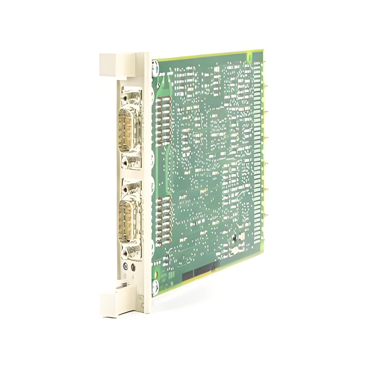
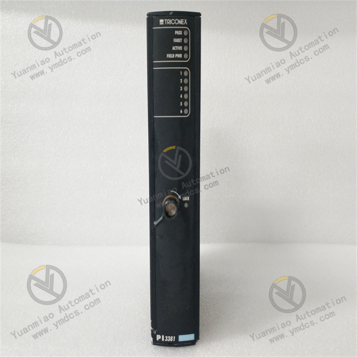
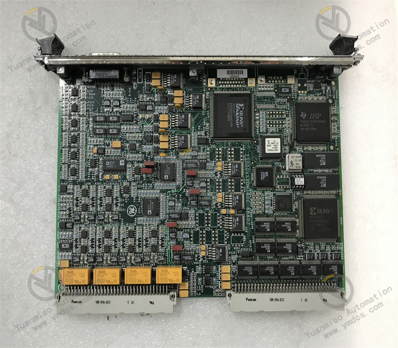
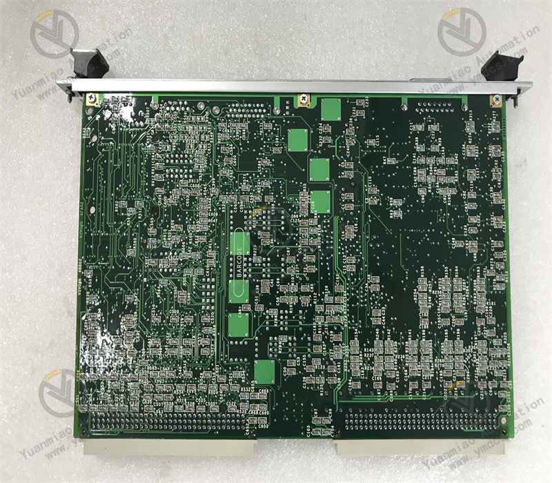
IS200VSVOH1B is a dedicated VME Servo Control Output Board (VSVO) for GE Speedtronic Mark VI / Mark VIe turbine control systems. It serves as the core I/O module for valve servo‑control of gas and steam turbines, and is critical hardware for precise regulation of unit fuel valves, steam valves and inlet valves.
Designed for continuous‑operation conditions in power plants, this board integrates servo drive output, LVDT excitation power supply, valve‑position feedback acquisition and pulse flow signal input. It supports simplex and TMR triple‑modular‑redundant fault‑tolerant architectures, and realizes closed‑loop control for electro‑hydraulic servo valves when cooperating with servo terminal boards.
As an original GE industrial control board with no universal replacement, it is widely used for routine maintenance, fault replacement and system expansion & retrofitting of heavy‑duty gas turbine, steam turbine and combined‑cycle power‑plant control systems, meeting requirements for high‑precision dynamic regulation and safety interlock control of turbine units.
2. Functions and Features
2.1 Core Functions
Multi‑channel Servo Drive Control: Equipped with 4 independent servo control channels to drive four electro‑hydraulic servo valves simultaneously. It outputs precise control current for continuous opening regulation of gas‑turbine fuel valves, steam‑turbine steam valves and inlet regulating valves, adapting to dynamic unit control under variable‑load and off‑design conditions.
LVDT Excitation and Valve‑position Feedback Acquisition: Built‑in LVDT excitation power unit supplies stable excitation power for up to 6 sets of valve‑position displacement sensors. It acquires high‑precision LVDT valve‑position feedback signals to form a complete closed‑loop valve‑position regulation circuit and guarantee accurate valve positioning.
Pulse‑rate Flow Signal Input: Supports pulse‑type flow signal acquisition for real‑time monitoring of unit fuel flow and medium delivery rate, providing accurate raw data for unit load calculation, fuel‑air ratio matching and process‑parameter optimization.
Redundant Fault‑tolerant Control Compatibility: Natively compatible with the TMR triple‑modular‑redundant architecture of Mark VI systems. It implements cross‑comparison and fault‑tolerant voting for three‑way signals. Single‑channel faults will not affect overall valve‑regulation logic, preventing unit load fluctuation or shutdown caused by single‑point failures.
Full‑scope Hardware Self‑diagnosis: Continuously monitors servo output loops, LVDT excitation status, signal acquisition links, board power supply and chip operating conditions. Automatic fault alarms and status‑LED indications enable accurate localization of channel faults, circuit open‑circuits, signal abnormalities and other issues.
Standardized Bus Data Interaction: High‑speed communication with the main controller via the VME backplane bus. It receives real‑time regulation commands from the main unit and uploads valve‑position status and flow data, ensuring real‑time performance and consistency of command distribution and data feedback within the control system.
2.2 Product Features
High‑precision Closed‑loop Regulation Performance: Adopts high‑resolution signal acquisition and servo‑output design, delivering high valve‑position control accuracy, fast response and small steady‑state deviation, perfectly satisfying millisecond‑level fast dynamic‑regulation requirements of gas turbines.
Redundant and Reliable Operation Architecture: Supports both simplex and TMR triple‑modular‑redundant operation modes with strong fault tolerance, complying with 24/7 safe and stable operation standards for critical power‑plant units.
Adaptability to Severe Industrial Conditions: Uses military‑grade SMD components and anti‑interference PCB layout. It offers excellent dust‑proof, shock‑proof, moisture‑proof and EMC performance, tolerating harsh plant environments with high temperature, mechanical vibration and heavy electromagnetic interference.
Full Original‑equipment Compatibility: Standard VME slot‑mount form‑factor. Backplane interfaces, communication protocols and electrical parameters are fully compatible with the full GE Mark VI / VIe control‑system series. No wiring or system‑configuration modification is required upon replacement; on‑line maintenance swap is supported.
Integrated Multi‑function Design: Combines servo drive, LVDT excitation, valve‑position acquisition and pulse‑flow input functions. It simplifies cabinet hardware layout, reduces potential fault points and lowers maintenance costs.
3. Specifications
| Parameter Item | Technical Specification |
|---|---|
| Model | IS200VSVOH1B |
| Device Type | VSVO Servo Control Output Board for Mark VI / VIe Systems |
| Channel Configuration | 4 independent servo‑control output channels; supports multi‑channel LVDT valve‑position acquisition |
| Core Functions | Servo‑valve drive, LVDT excitation power supply, valve‑position feedback acquisition, pulse flow input |
| Redundancy Mode | Simplex / TMR Triple‑Modular‑Redundant fault‑tolerant operation |
| Bus Standard | VME industrial backplane bus |
| Operating Power Supply | Standard cabinet DC24V power supply with on‑board voltage‑stabilizing circuit |
| Operating Temperature | -40℃ ~ +70℃ |
| Ambient Humidity | ≤95%RH, non‑condensing |
| Installation Method | Standard VME rack slot‑mount installation; hot‑swap replacement supported |
| Compatible Field Devices | Electro‑hydraulic servo valves, LVDT valve‑position sensors, pulse‑type flow detectors |
| Applicable Systems | GE Speedtronic Mark VI / Mark VIe Gas / Steam Turbine Control Systems |
4. Working Principle
The IS200VSVOH1B servo board implements a full closed‑loop workflow: Command Reception → Signal Output → Valve‑position Acquisition → Closed‑loop Calculation → Self‑diagnosis & Monitoring.
During system operation, the board receives real‑time valve‑opening commands from the main controller over the VME backplane bus. After internal DSP computation and signal amplification, accurate drive current is output to field electro‑hydraulic servo valves to control spool movement and valve opening variation. Meanwhile, the board continuously outputs excitation voltage to power LVDT valve‑position sensors, and acquires analog valve‑position feedback signals. After filtering, waveform shaping and calibration, processed signals are sent back to the main control system.
Based on deviations between set‑point opening and actual valve position, the main controller dynamically corrects servo output commands to achieve high‑precision closed‑loop valve regulation. For pulse‑type flow signals, the board performs pulse counting and rate conversion; real‑time flow data is generated for unit‑load and combustion‑logic calculation.
Under TMR redundant architecture, data from multiple boards is cross‑compared and voted, and abnormal signals are automatically rejected to avoid regulation deviations caused by single‑channel faults. The board continuously self‑checks loop conditions, power‑supply status and signal links. Alarms are triggered and faulty channels are isolated upon anomalies to guarantee stable and reliable operation of the unit valve‑control system.
5. Application Scenarios
Heavy‑duty Gas‑Turbine Control Systems: Closed‑loop servo regulation for gas‑turbine fuel valves, inlet valves and exhaust bypass valves. It delivers precise valve‑position control for unit startup, shutdown, load ramping and steady‑state operation, ensuring combustion stability and unit efficiency.
Steam‑Turbine Control Systems: Servo drive control for steam‑turbine main steam valves, governing valves and extraction valves. Combined with valve‑position feedback signals, it realizes accurate regulation of turbine speed, load and pressure to meet grid frequency‑regulation and peak‑shaving requirements.
Combined‑cycle Power‑plant Control: Coordinates servo‑valve control and flow monitoring for gas‑turbine and steam‑turbine auxiliary valves. It achieves coordinated multi‑device regulation for combined‑cycle units and improves overall unit stability and power‑generation efficiency.
Industrial Turbine Power‑equipment Control: Applied in servo‑valve regulation systems for large‑scale industrial turbines and compressor units, realizing closed‑loop precise control of medium flow, pressure and rotational speed.
Legacy‑unit Maintenance and Retrofit: Fully compatible with legacy GE Mark VI control systems. Aged or faulty servo boards can be directly replaced without modifying cabinet wiring, system configuration or control logic, enabling fast equipment repair and system expansion.
6. Common Faults and Troubleshooting
6.1 No Valve Movement, Servo Regulation Failure
Fault Causes: Damaged servo output channels on the board; drive‑circuit failure; abnormal LVDT excitation; failure to receive commands over the VME bus; open‑circuit field servo‑valve loop.Solutions: Inspect board power supply and bus‑link communication; measure servo output current and LVDT excitation voltage to locate channel faults; verify continuity of field servo‑valve and wiring loops; clean board edge connectors and rack slots then power‑cycle for system reset; replace original IS200VSVOH1B board in case of hardware channel damage.
6.2 Valve‑position Oscillation, Degraded Regulation Accuracy, Frequent Load Jitter
Fault Causes: Signal‑acquisition drift on board; aged filtering circuitry; degraded servo‑output precision; LVDT signal interference; abnormal redundant‑data voting.Solutions: Rectify field shielding and grounding to eliminate electromagnetic interference; calibrate valve‑position acquisition parameters and troubleshoot sensor faults; compare data from redundant channels to identify defective board; replace spare part directly when board‑induced accuracy drift cannot be calibrated to restore regulation stability.
6.3 Loss of LVDT Valve‑position Feedback, No Valve‑position Signal
Fault Causes: Failed LVDT excitation circuit on board; damaged acquisition channels; open‑circuit external‑sensor wiring; short‑circuited signal loop.Solutions: Measure board excitation output voltage to verify board power‑supply performance; troubleshoot field LVDT wiring and sensor conditions section by section; replace original board once external wiring and device faults are ruled out and board hardware failure is confirmed.
6.4 Abnormal Pulse Flow Data, Flow‑acquisition Failure
Fault Causes: Defective pulse‑acquisition channels on board; abnormal signal reception; corrupted counting logic; faulty field pulse‑sensor output.Solutions: Verify output signals from upstream pulse sensors; inspect signal wiring and shielding conditions; power‑cycle the system to reset board acquisition logic; replace the board when acquisition function fails to restore flow‑monitoring capability.
6.5 Board Communication Loss, System Reports VSVO Module Fault
Fault Causes: Poor VME‑bus contact; abnormal board firmware; defective backplane links; hardware aging caused by long‑term high‑temperature operation.Solutions: Power off, clean board edge connectors and rack backplane slots, then reinstall and fasten the board; flash matching original‑equipment firmware; improve cabinet heat‑dissipation and ambient operating conditions; replace with original spare part of the same model if faults recur repeatedly.