Description
1. Overview
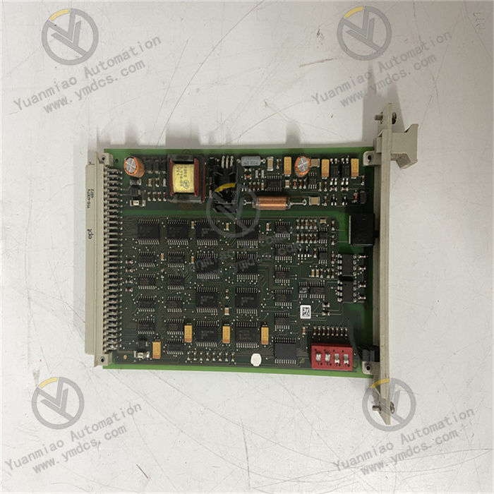
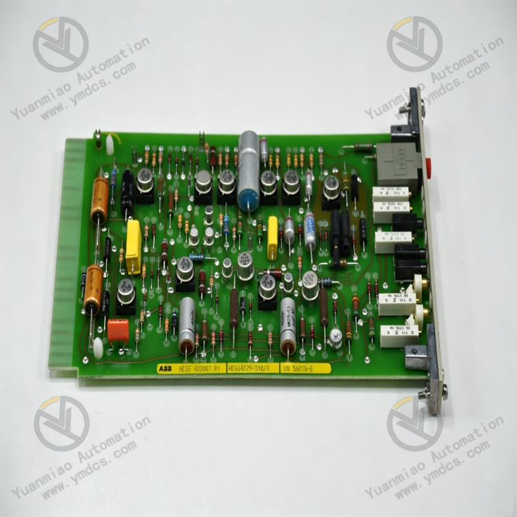
ABB UV5627B‑E, part number HEIE420007R0001, is a dedicated bus coupler / signal conditioning interface board under ABB industrial control systems. It belongs to ABB high‑end industrial measurement‑control and power control hardware portfolio, acting as a core signal conversion and isolation module for integrated industrial control systems, unit auxiliary control systems and electric drive control systems.
This board features industrial signal isolation, bus data forwarding and field‑signal conditioning adaptation. Designed for harsh industrial environments such as power generation, heavy industry and chemical processing, it delivers high anti‑interference performance, outstanding stability and long‑term continuous operation capability. As an original‑equipment dedicated spare part with no universal alternative, it is widely deployed for fault replacement, equipment maintenance, system expansion and legacy‑hardware retrofitting of existing ABB integrated control systems. It offers full compatibility with rack backplanes, power supply architecture and system configuration logic of the corresponding product series.
2. Functions and Features
2.1 Core Functions
Industrial Signal Isolation and Conditioning: Provides galvanic isolation, waveform shaping and signal filtering for field‑sourced analog and discrete signals. It suppresses industrial noise and signal jitter, normalizes non‑standard signals, ensures accurate and stable input, and prevents system misjudgment induced by interference.
Bus‑data Coupling and Forwarding: Performs coupling and relay between the internal system bus and field I/O links. It enables bidirectional data interaction between the main controller and field measurement points / actuators, delivers command distribution and status‑data feedback, and maintains unobstructed bus communication.
Signal‑level Adaptation and Conversion: Compatible with standard industrial control signals. It performs level matching and conversion for multi‑specification signals, resolves incompatibility between field‑device signals and main‑system signals, and supports access of various industrial measurement points.
Link Status Monitoring and Alarm: Real‑time monitoring of signal input links, bus communication and power‑supply conditions. It accurately identifies open circuits, signal anomalies and link failures, uploads fault information and provides data support for maintenance troubleshooting.
Auxiliary System Hardware Fault Tolerance: Galvanic‑isolation design blocks reverse voltage, leakage current and electromagnetic interference propagating from the field into the main control system. It protects core control units, reduces overall hardware failure risks and improves system operational safety.
2.2 Product Features
Industrial‑grade High Reliability: Adopts industrial‑grade components and standardized industrial design. Supports 24‑hour non‑stop long‑term operation with low drift and low failure rate, suitable for continuous‑production scenarios such as power plants and heavy‑industry facilities.
Superior EMC Performance: Complies with industrial EMC standards. Withstands heavy electromagnetic interference generated by high‑voltage equipment, frequency converters and high‑power units without signal distortion or fluctuation.
Full Original‑equipment Compatibility: Standard rack‑mount card form‑factor. Backplane interfaces, power‑supply parameters and communication protocols fully match ABB counterpart control systems. No modification to system configuration or wiring logic is required upon replacement.
Easy Maintenance without On‑site Commissioning: Factory‑calibrated accuracy and preset parameters enable plug‑and‑play rapid replacement. No on‑site calibration or program debugging is needed, greatly shortening maintenance downtime.
Harsh‑environment Adaptability: Wide‑temperature operation, dust‑proof, moisture‑proof and vibration‑resistant construction. Adapts to severe on‑site conditions including high temperature, high humidity, dust and mechanical vibration.
3. Specifications
| Parameter Item | Technical Specification |
|---|---|
| Model | UV5627B‑E |
| Part Number | HEIE420007R0001 |
| Device Type | Industrial Bus Coupler / Signal Conditioning & Isolation Board |
| Core Functions | Signal isolation, filtering & waveform shaping, bus coupling, data forwarding, level adaptation |
| Operating Power Supply | Standard Industrial DC24V Control Power Supply |
| Isolation Method | Full galvanic isolation; insulation protection between input side and bus side |
| Operating Temperature Range | 0℃ ~ +60℃ |
| Storage Temperature Range | -20℃ ~ +70℃ |
| Ambient Humidity | ≤95%RH, non‑condensing |
| Ingress Protection | IP20 |
| Installation Method | Standard rack slot‑mount installation |
| Applicable Systems | ABB integrated industrial measurement‑control, electric drive and unit auxiliary control systems |
4. Working Principle
ABB UV5627B‑E operates under a closed‑loop workflow: Signal Input → Protection & Filtering → Galvanic Isolation → Level Adaptation → Bus Coupling & Forwarding → Status Diagnosis.
Monitoring signals and control feedback signals from field devices are fed into the front‑end terminals of the board. Surge over‑voltage and over‑current protection circuits protect the board and downstream main‑control hardware against transient electrical shocks. Signals then pass through multi‑stage filtering and waveform‑shaping units to eliminate electromagnetic noise and pulse jitter from field environments and produce standardized stable signals.
Normalized signals are fully galvanically isolated between field devices and the main‑control system to block ground‑potential differences, leakage and interference from feeding back into the system and safeguard main‑control hardware. The isolated signals go through level‑adaptation conversion to comply with system bus standards. The bus‑coupling unit performs data packaging, parsing and bidirectional forwarding to distribute main‑controller commands and upload field status data. Link conditions are continuously self‑monitored during runtime. Faults are actively reported upon abnormality to guarantee stable signal transmission and reliable logic execution of the whole control system.
5. Application Scenarios
Power‑plant Unit Auxiliary Control Systems: Measurement‑control systems for auxiliary equipment of thermal‑power, hydro‑power and gas‑turbine units. Performs signal isolation and bus‑data relaying for auxiliary equipment to ensure stable operation of auxiliary interlocks, status monitoring and automatic control.
Industrial Electric‑drive Control Systems: Supporting systems for large variable‑frequency drives, motor speed‑regulation and power‑control equipment. Realizes drive‑signal conditioning and bus‑communication coupling to stabilize equipment regulation accuracy.
Chemical / Heavy‑industry Integrated Control Systems: Automation control systems for chemical plants and heavy‑industry equipment. Isolates heavy field interference signals and guarantees accurate acquisition of process measurement points and reliable interlock‑logic execution.
Legacy‑equipment Maintenance and Retrofit: Replaces aged and faulty signal‑conditioning and bus‑coupling boards of ABB corresponding series. Fully compatible with original racks, wiring and system programs. No secondary configuration or commissioning required for fast equipment repair and system expansion.
6. Common Faults and Troubleshooting
6.1 No Signal Feedback, Complete Loss of Measurement‑point Data
Fault Causes: Abnormal DC24V power supply to the board; poor slot contact; open‑circuit front‑end signal loop; damaged signal‑processing circuitry on the board.Solutions: Inspect rack supply voltage, fuses and power loops; power off, clean board edge connectors and rack slots, then re‑insert and secure the board; troubleshoot continuity of field signal cables section by section to rule out wiring faults; replace original UV5627B‑E board when hardware circuitry is damaged.
6.2 Frequent Data Fluctuation and Unstable Signal Readings
Fault Causes: Aged filtering circuitry; degraded galvanic‑isolation performance; severe on‑site electromagnetic interference; non‑standard shielding and grounding.Solutions: Rectify equipment shielding and grounding to eliminate interference caused by multi‑point grounding or poor contacts; remove dust and oxidation from the board and optimize heat‑dissipation conditions; replace the board directly when filtering and isolation functions fail to restore signal stability.
6.3 Bus Communication Breakdown, Abnormal Data Forwarding
Fault Causes: Malfunction of bus‑coupling module; faulty backplane bus links; corrupted board communication firmware; oxidized interfaces with poor contact.Solutions: Verify integrity of backplane bus interfaces and wiring; power‑cycle the system to reset communication status; clean oxidized bus‑interface contacts; replace original board if communication cannot be recovered.
6.4 Deviated Readings and Loss of Accuracy for Partial Measurement Points
Fault Causes: Aged signal‑conditioning circuitry; parameter drift after long‑term operation; degraded level‑conversion precision.Solutions: Calibrate measurement‑point accuracy against reference signals and eliminate external‑device faults; replace the board directly when board‑induced accuracy drift and conditioning‑function failure are confirmed to restore system acquisition precision.
6.5 System Reports Link Fault and Hardware‑abnormal Alarms
Fault Causes: Abnormal board firmware execution; hardware self‑test errors; component aging and failure due to prolonged high‑temperature operation.Solutions: Power‑cycle the unit to reset operating status; check rack heat dissipation and ambient temperature and improve operating conditions; treat the board as defective and replace with original spare part of the same model if faults recur repeatedly.