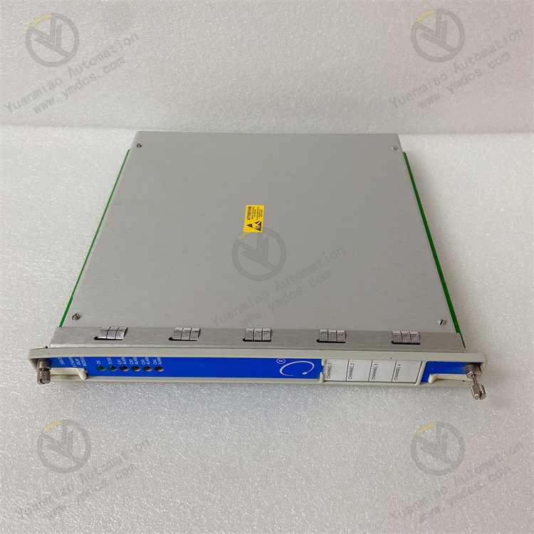
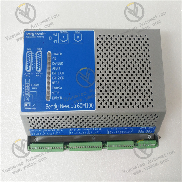
Description
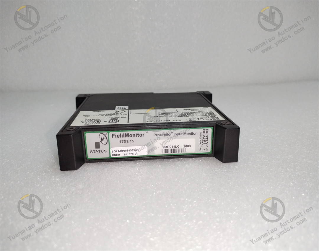
Bently Nevada 1701/15 is a field monitor proximity input monitor for radial vibration and thrust position monitoring. Functional Features Dual-channel design: As a dual-channel device, it can receive signals from proximity probes through relevant sensor input/output or internal preamplifier modules. It can process and monitor signals of both channels simultaneously, improving the monitoring efficiency and accuracy. Signal processing and conversion: It converts the received signals into appropriate measurement units, such as converting electrical signals into actual measured values of physical quantities like displacement and vibration velocity, facilitating operators to intuitively understand the operating status of the equipment. Alarm function: It can compare the measured values with the user-programmable alarm set values. When the measured values exceed the set alarm thresholds, it generates corresponding alarm signals and transmits them to the main control system, promptly reminding operators to take corresponding measures to protect the equipment from potential damage. Data output: It can provide the current values of the measured parameters to the control system for indication and trend analysis. Operators can view the operating parameters of the equipment in real time through the control system and analyze the trend of parameter changes to detect potential problems of the equipment in advance. Self-detection: It has a built-in self-detection function, allowing the monitor to evaluate its own integrity and the status of the connected sensors. When there are problems with the monitor or the connected sensors, it can detect them and send notifications, making it convenient for maintenance personnel to troubleshoot and repair in a timely manner.
 Technical Specifications
Measurement range: It usually supports a measurement range of 4 - 20mA, which can be adjusted according to actual application requirements.
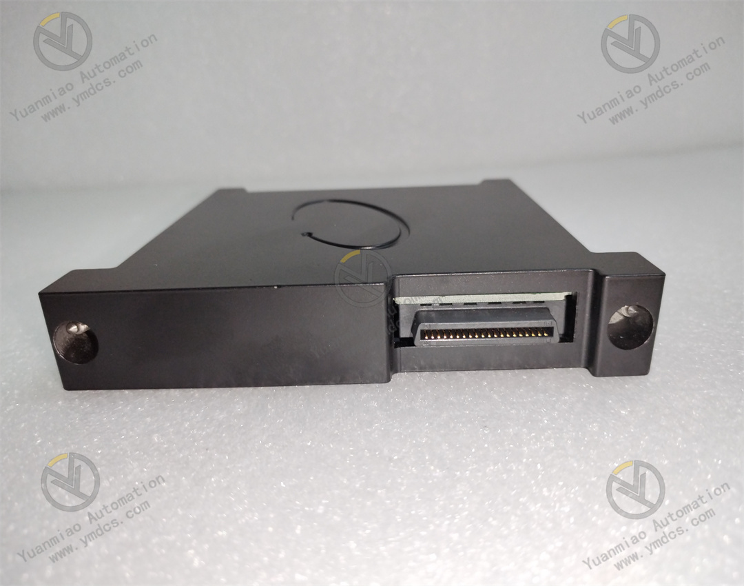
Input type: It is proximity sensor input, suitable for connecting various types of proximity probes to obtain relevant measurement signals of the equipment.
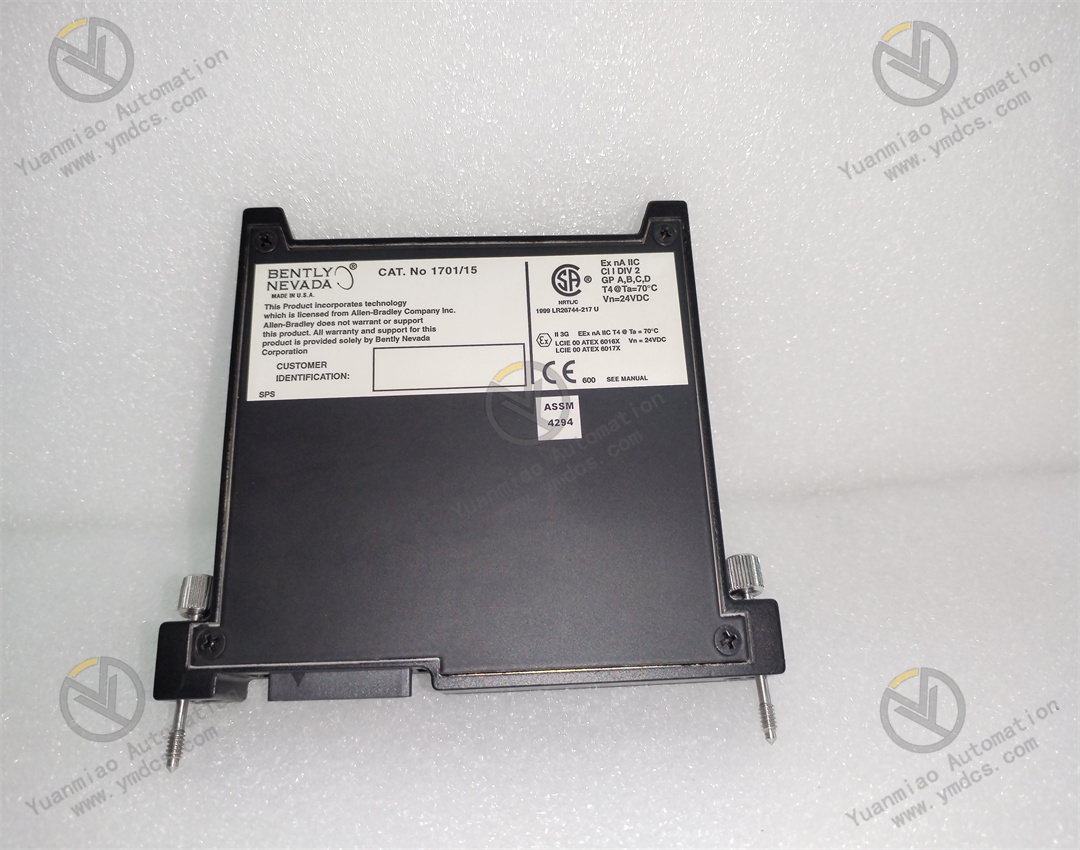
Operating temperature: The operating temperature range is generally from - 40°C to + 85°C, enabling stable operation in relatively harsh industrial environments.
Output frequency: The output frequency is 50kHz, which can meet the data update rate requirements of most industrial control systems.
Power supply: It is powered by a 24V DC power supply, with good stability and anti-interference ability.
Accuracy: The accuracy can reach ±0.2% F.S., providing high-precision measurement results and ensuring accurate monitoring of the equipment status.
Application Areas: Bently Nevada focuses on the online condition monitoring and mechanical protection of rotating machinery. This monitor is suitable for various industrial scenarios where precise monitoring of the radial vibration and thrust position of rotating machinery is required, such as fans, compressors, water pumps, steam turbines and other rotating mechanical equipment in enterprises like power plants, steel plants, chemical plants, and cement plants. By monitoring the key parameters of these devices in real time, it can achieve fault warning and diagnosis of the equipment, ensuring the safe and stable operation of the equipment.
Technical Specifications
Measurement range: It usually supports a measurement range of 4 - 20mA, which can be adjusted according to actual application requirements.
Input type: It is proximity sensor input, suitable for connecting various types of proximity probes to obtain relevant measurement signals of the equipment.
Operating temperature: The operating temperature range is generally from - 40°C to + 85°C, enabling stable operation in relatively harsh industrial environments.
Output frequency: The output frequency is 50kHz, which can meet the data update rate requirements of most industrial control systems.
Power supply: It is powered by a 24V DC power supply, with good stability and anti-interference ability.
Accuracy: The accuracy can reach ±0.2% F.S., providing high-precision measurement results and ensuring accurate monitoring of the equipment status.
Application Areas: Bently Nevada focuses on the online condition monitoring and mechanical protection of rotating machinery. This monitor is suitable for various industrial scenarios where precise monitoring of the radial vibration and thrust position of rotating machinery is required, such as fans, compressors, water pumps, steam turbines and other rotating mechanical equipment in enterprises like power plants, steel plants, chemical plants, and cement plants. By monitoring the key parameters of these devices in real time, it can achieve fault warning and diagnosis of the equipment, ensuring the safe and stable operation of the equipment.
 Common Faults and Solutions of Bently Nevada 1701/15
1. No display or abnormal display
Fault phenomenon: The monitor screen has no display, or there are abnormal situations such as blurring, garbled characters, and flickering.
Possible reasons:
Power failure, such as power interruption, unstable voltage, or damage to the power module.
Loose or damaged connection of the display module.
Internal circuit board failure.
Solutions:
Check the power supply to ensure that the voltage is within the specified range (usually 24V DC), check the power line for open circuits or short circuits, and try to replace the power module.
Check the connection plug of the display module to ensure a firm connection. If it is damaged, replace the display module.
If the above methods are ineffective, it may be an internal circuit board failure, and you need to contact the manufacturer or professional maintenance personnel for repair.
Common Faults and Solutions of Bently Nevada 1701/15
1. No display or abnormal display
Fault phenomenon: The monitor screen has no display, or there are abnormal situations such as blurring, garbled characters, and flickering.
Possible reasons:
Power failure, such as power interruption, unstable voltage, or damage to the power module.
Loose or damaged connection of the display module.
Internal circuit board failure.
Solutions:
Check the power supply to ensure that the voltage is within the specified range (usually 24V DC), check the power line for open circuits or short circuits, and try to replace the power module.
Check the connection plug of the display module to ensure a firm connection. If it is damaged, replace the display module.
If the above methods are ineffective, it may be an internal circuit board failure, and you need to contact the manufacturer or professional maintenance personnel for repair.
2. Abnormal measurement values or large fluctuations Fault phenomenon: The measured vibration values or thrust position values deviate significantly from the normal range, or the values fluctuate violently. Possible reasons: Sensor failure, such as probe damage, cable breakage, or poor insulation. Installation problems, such as incorrect probe installation position, inappropriate clearance, or loose fixation. Signal interference, with strong electromagnetic interference sources nearby. Failure of the internal signal processing circuit of the monitor. Solutions: Check the sensor and cable, and use tools such as a multimeter to test the output signal of the sensor. If it is damaged, replace the sensor or cable. Recheck the installation position and clearance of the probe to ensure that they meet the requirements specified by the manufacturer, and tighten the probe fixing screws. Investigate whether there are strong electromagnetic interference sources around, such as motors and transformers, and take shielding measures or adjust the equipment position. If the problem still cannot be solved, it may be an internal fault of the monitor, and you need to contact the manufacturer for repair or calibration.
3. False alarm triggering or no alarm triggering
Fault phenomenon: The alarm is triggered when the system does not reach the alarm set value, or the alarm is not triggered when the alarm value is reached.
Possible reasons:
Incorrect setting of the alarm set value.
Drift of the alarm threshold, which may be caused by long-term use or changes in the ambient temperature.
Failure of the alarm output circuit.
Solutions:
Recheck and set the alarm set value to ensure that it meets the equipment operation requirements.
Use a standard signal source to calibrate the monitor and adjust the alarm threshold to the accurate value.
Check the alarm output circuit, test whether the alarm relay or output terminal works normally. If it is damaged, replace the corresponding components.
4. Communication failure
Fault phenomenon: It is unable to communicate with the host computer or other devices, or the communication data transmission is unstable.
Possible reasons:
Incorrect communication parameter settings, such as mismatches in baud rate and address.
Poor connection or damage to the communication cable.
Failure of the communication interface module.
Solutions:
Check the communication parameter settings to ensure consistency with those of the host computer or other devices.
Check the communication cable connection and replace the damaged cable.
Test the communication interface module. If it is faulty, replace the interface module.
5. Self-detection failure Fault phenomenon: An error code is displayed or a detection failure prompt appears during the self-detection process of the device. Possible reasons: Internal hardware failure, such as damage to circuit board components. Software program error or data loss. Solutions: Try to restart the device to clear possible temporary errors. If the failure still occurs after restarting, contact the manufacturer for firmware upgrade or program reset. If the problem persists, it may be a hardware failure, and professional personnel are required for repair or component replacement.

6. Sensor connection failure
Fault phenomenon: A sensor connection error is displayed or there is no signal input.
Possible reasons:
The sensor cable is not correctly connected to the monitor.
Open circuit or short circuit of the sensor cable.
Damage to the sensor probe.
Solutions:
Check the connection between the sensor cable and the monitor to ensure that the plug is tightly inserted without looseness or oxidation.
Use a multimeter to detect the continuity of the cable. If there is an open circuit or short circuit, replace the cable.
Test the output signal of the sensor probe. If there is no signal output, replace the probe.
7. Abnormal output signal Fault phenomenon: The 4 - 20mA output signal exceeds the range or is unstable. Possible reasons: Failure of the output circuit. Load impedance mismatch. Internal calibration problem. Solutions: Check the output circuit, test the voltage and current of the output terminal. If there is an abnormality, replace the relevant components. Ensure that the load impedance is within the specified range (usually 250 - 600Ω). Use a standard signal source to calibrate the output and adjust it to the accurate value. Precautions Before any troubleshooting and maintenance operations, be sure to cut off the power supply of the device to ensure safety. For complex faults or problems involving internal circuits, it is recommended to contact the professional technical support personnel or authorized maintenance center of Bently Nevada for handling. Regularly maintain the device, such as cleaning the dust and checking the connection components, which can reduce the probability of faults.