Description
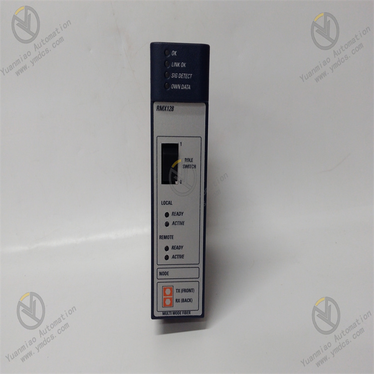
GE IC695RMX128
I. Overview
II. Key Features
Large-Capacity Redundant Storage to Meet Complex System Requirements
- Built-in 128MB redundant data memory (DDR SDRAM), supporting superimposed expansion with the CPU's built-in memory. The maximum system data memory can be expanded to 256MB, meeting the needs of large-scale control logic, massive process data storage, and long-cycle fault recording.
- Adopts a "master-standby dual-copy" redundant storage architecture. Critical data is synchronously copied to dual storage areas in real-time. When either storage area fails, it automatically switches to the standby area to ensure data integrity and availability.
Redundant Synchronization and Hot-Swappable Design to Ensure System Continuity
- Supports data synchronization for RX3i redundant systems (dual CPU hot standby). The module communicates with the master and standby CPUs in real-time to ensure complete consistency of data between the master and standby systems, with no data loss or deviation during fault switching.
- Complies with RX3i series hot-swapping standards (requires system support for redundant configuration). The module can be inserted or removed while the PLC system is running, enabling maintenance and replacement without shutting down the system, thus improving system availability and maintenance efficiency.
High Reliability and Data Protection
- Adopts industrial-grade storage chips and enhanced electromagnetic compatibility (EMC) design, passing IEC 61000-4 anti-interference tests (surge ±2kV, ESD ±8kV). Operating temperature range: -20℃~+60℃; humidity: 5%-95% (non-condensing); MTBF (Mean Time Between Failures) ≥200,000 hours.
- Integrates data verification and Error Correction Code (ECC) functions, which can automatically detect and repair minor errors during memory data transmission and storage. Supports super capacitor backup (requires matching with the CPU module's super capacitor), with critical data retention ≥72 hours after power failure.
Seamless Compatibility and Flexible Expansion
- Fully compatible with all RX3i series CPU models (e.g., IC695CPU310/330/430), supporting installation in RX3i standard racks (3-slot/5-slot/7-slot/10-slot). Can be mixed with other RX3i modules (analog, digital, communication modules) without additional adapter hardware.
- Supports multi-module cascading expansion. Up to 2 IC695RMX128 modules can be installed simultaneously, and the maximum system data memory can be expanded to 384MB, adapting to the needs of redundant control systems of different scales.
Intelligent Diagnosis and Status Feedback
- Equipped with LED status indicators (power light, run light, redundant synchronization light, fault light) on the top of the module, providing real-time feedback on module power supply status, working status, redundant synchronization progress, and fault information. Fault visualization facilitates quick troubleshooting.
- Supports reading module status and diagnostic data via Proficy Machine Edition (PME) software, enabling remote monitoring of redundant synchronization status, memory usage, and fault records, simplifying maintenance processes.
III. Technical Specifications
| Category | Detailed Specifications |
|---|---|
| Product Type | RX3i series redundant memory expansion module |
| Core Functions | Data memory expansion, redundant data backup, data synchronization, and fault switching |
| Storage Capacity | 128MB DDR SDRAM (single module); supports 2-module cascading, maximum expansion to 384MB |
| Redundant Features | Master-standby dual-copy storage, real-time data synchronization, automatic fault switching, ECC error correction |
| Compatibility | Compatible with all RX3i series CPU models (IC695CPU310/330/430, etc.), RX3i standard racks, and PME software (V9.0 and above) |
| Hot-Swap Support | Supported (requires system redundant configuration) |
| Electrical Parameters | Operating power supply: Backplane power (5VDC, provided by RX3i rack); Power consumption: ≤3W (single module) |
| Data Retention | Supports super capacitor backup (dependent on CPU module's super capacitor), data retention ≥72 hours after power failure |
| Environmental Adaptability | Operating temperature: -20℃~+60℃; Storage temperature: -40℃~+85℃; Humidity: 5%-95% (non-condensing); Vibration: 10g (10-2000Hz) |
| Installation Method | RX3i standard rack plug-in installation (compatible with all RX3i rack models) |
| Physical Dimensions | Width: 36mm; Height: 100mm; Depth: 165mm (excluding connectors) |
| Weight | Approximately 0.3kg |
| Diagnostic Functions | Memory error diagnosis, redundant synchronization abnormality alarm, power fault monitoring, module communication diagnosis |
| Status Indicators | Power light (PWR, green), Run light (RUN, blue), Redundant Synchronization light (SYNC, yellow), Fault light (FAULT, red) |
IV. Working Principle
Memory Expansion and Data Allocation: After the module is connected to the RX3i rack, it establishes communication with the CPU via the backplane bus. The 128MB memory space is divided into "User Data Area", "Redundant Backup Area", and "Fault Record Area", which are automatically allocated to the system memory address space, forming superimposed expansion with the CPU's built-in memory.
- Redundant Data Storage: Critical data in the user program (such as process parameters, equipment status, and control variables) is written to the "User Data Area" in real-time and synchronously copied to the "Redundant Backup Area", forming dual-copy storage to ensure data redundancy.
Real-Time Synchronization and Verification: In redundant systems, the module interacts with the master and standby CPUs in real-time. After data modification on the master CPU, it is immediately synchronized to the corresponding module memory of the standby CPU with a synchronization delay ≤1ms. Meanwhile, real-time verification of stored data is performed through the ECC error correction algorithm to detect and repair single-bit errors.
- Fault Switching and Data Recovery: If a failure of the master storage area (e.g., memory chip damage) or CPU switching is detected, the module automatically enables the data in the "Redundant Backup Area" to ensure continuous execution of system control logic without data loss. After the fault is resolved, it automatically synchronizes data between the backup area and the master storage area to restore the redundant state.
- Diagnosis and Feedback: Real-time monitoring of module power supply, memory status, and redundant synchronization links. If an abnormality is detected (e.g., synchronization failure, memory error, communication interruption), the fault light is immediately triggered, and the fault code is uploaded to the CPU via the backplane bus. Detailed fault information can be read through PME software.
V. Operation Guide
1. Installation Steps
Installation Environment
- Install in an RX3i standard PLC control cabinet, away from strong electromagnetic interference sources (such as frequency converters, power modules) and high-temperature heat sources. Reserve a heat dissipation gap of ≥5mm on both sides to ensure good ventilation in the cabinet and avoid high temperatures affecting the stability of memory chips.
Mechanical Installation
- Confirm that the rack power supply is disconnected. Insert the module into any available I/O slot of the RX3i standard rack (it is recommended to install it close to the CPU module), ensuring full contact between the module and the rack backplane contacts. Lock the fixing buckles on both sides for secure installation without looseness.
- When cascading multiple modules, maintain a spacing of ≥10mm between modules to avoid mutual heat dissipation interference. Hot-swapping is only supported for systems with redundant configurations; non-redundant systems require power-off before insertion/removal.
Wiring Specifications
- Power Wiring: No separate wiring is required. 5VDC power is obtained from the RX3i power supply module through the backplane bus. Before installation, confirm that the output voltage of the power supply module is stable (5VDC±0.2VDC).
- Grounding Requirements: Reliably connect the rack's ground terminal to the control cabinet's ground bar with a ground resistance ≤4Ω to enhance anti-interference capability and avoid memory data errors caused by electromagnetic interference.
2. Configuration and Debugging
Hardware Compatibility Check
- Confirm the compatibility of the module with the RX3i CPU model (e.g., IC695CPU330) and rack model. Check that the rack power supply voltage (5VDC) meets the module's requirements. For multi-module cascading, confirm that the CPU supports the expanded memory capacity (maximum 384MB).
Software Configuration (Proficy Machine Edition)
- Install PME software (Version V9.0 or above), create a new RX3i project, add the IC695RMX128 module, select the corresponding rack slot position, and import the module driver library.
- Memory Configuration: Set the module memory allocation scheme in the software (e.g., 80MB for User Data Area, 40MB for Redundant Backup Area, 8MB for Fault Record Area), and enable redundant synchronization and ECC error correction functions.
- Redundant Configuration (Redundant Systems): Configure communication parameters for the master and standby CPUs, enable data synchronization between the module and the master/standby CPUs, and set the synchronization cycle (default 100ms, adjustable from 50ms to 500ms).
- Download the configuration file to the PLC, restart the CPU to make the configuration take effect, and the module will automatically establish communication with the CPU and initialize the memory.
Commissioning and Testing
- Memory Expansion Test: Monitor the total system memory capacity (CPU built-in memory + module expanded memory) via PME software to confirm that the expanded capacity meets the configuration requirements (e.g., 128MB CPU built-in memory + 128MB module memory = 256MB).
- Redundant Synchronization Test: In a redundant system, modify critical data on the master CPU side (such as process setpoints) and check the module memory data on the standby CPU side via PME software to verify real-time synchronization (delay ≤1ms).
- Fault Simulation Test: Disconnect the communication link between the master CPU and the module, observe whether the module automatically switches to the standby synchronization channel, whether the fault light is triggered, and whether data is normally retained.
3. Operation and Maintenance
Status Monitoring
- Real-time monitor the operation status via module LED indicators and PME software:
- Normal Status: PWR is always on (green), RUN is always on (blue), SYNC is always on (yellow, normal synchronization), FAULT is off;
- Fault Status: FAULT is always on (red), SYNC is flashing (synchronization abnormality). The fault code needs to be read via PME software (e.g., "F01 - Memory Error", "F02 - Synchronization Failure", "F03 - Power Supply Abnormality").
Regular Maintenance
- Monthly: Use dry compressed air to clean dust on the module surface and rack contacts, and check if the module is securely installed with no loose wiring terminals.
- Every 6 Months: Check memory usage via PME software (to avoid memory overflow), back up module configuration files and critical data; test the redundant synchronization function to verify the reliability of fault switching.
- Annually: Inspect whether internal capacitors and memory chips of the module are aging (such as capacitor bulging), test the effectiveness of the ECC error correction function; update PME software and module firmware (if required).
Notes
- Hot-swapping is prohibited in non-redundant systems. Before maintenance, cut off the rack power supply and wait for 3 minutes (for discharge completion) to avoid damaging the module or losing data.
- Module memory data relies on the CPU's super capacitor for backup. Regularly check the performance of the CPU's super capacitor to ensure normal data retention after power failure.
- For modules idle for more than 6 months, perform memory function tests and redundant synchronization verification before commissioning to confirm no abnormalities before connecting to the system.
4. Common Troubleshooting
| Fault Phenomenon | Possible Causes | Troubleshooting Methods |
|---|---|---|
| PWR light is off (no power supply) | Power supply module fault, poor contact with rack backplane, abnormal power supply voltage | Check if the power supply module output is 5VDC; re-plug the module to ensure good contact; test with a spare power supply module. |
| RUN light is off (not running) | Module not recognized, configuration error, CPU compatibility issue | Check if the module is recognized via PME software; verify configuration parameters (such as memory allocation); confirm compatibility between the CPU model and the module. |
| SYNC light is flashing (synchronization abnormality) | Redundant communication link fault, master-standby CPU asynchrony, configuration error | Check if the communication cable between the master and standby CPUs is loose/damaged; reconfigure redundant synchronization parameters; restart the PLC system to re-establish synchronization. |
| FAULT light is always on (fault alarm) | Memory error, ECC function failure, internal module fault | Read the fault code via PME software to locate the memory error area; disable and re-enable the ECC function; test with a module of the same model. |
| Memory expansion not effective | Configuration error, module not initialized, CPU memory limit | Verify the memory allocation configuration in PME software; restart the CPU to trigger module initialization; confirm the maximum expanded memory capacity supported by the CPU (≤384MB). |
| Data loss (after power failure) | CPU super capacitor failure, backup function not enabled | Test the performance of the CPU's super capacitor and replace if failed; check if the data backup configuration in PME software is enabled. |