Description
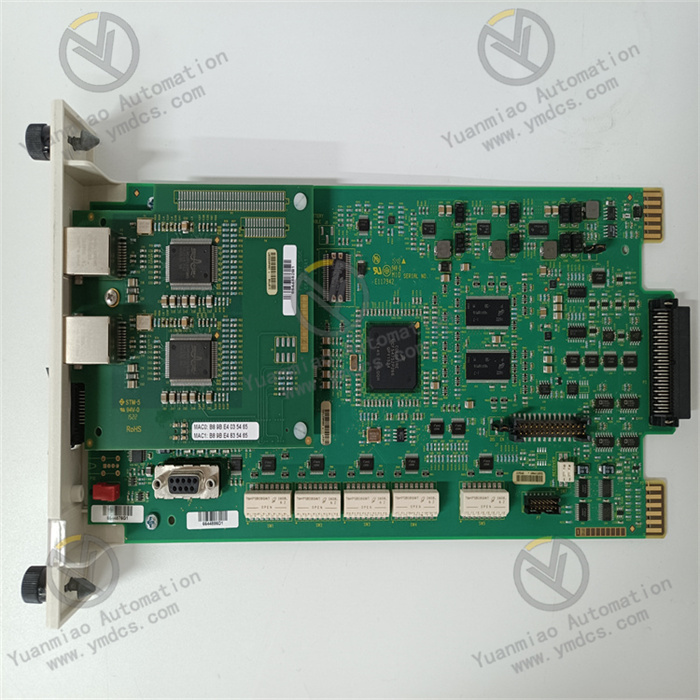
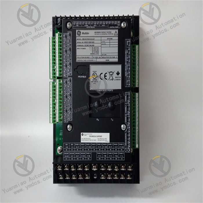
GE 369-HI-R-M-0-0-H-E
The GE 369-HI-R-M-0-0-H-E is a redundant relay output module, belonging to the high-end control system architecture of GE 90-70 PLC. As a core execution unit for high-reliability scenarios in industrial automation, it is widely used in key scenarios such as power system relay protection, safety interlocking of large chemical installations, high-temperature process control in metallurgy, rail transit equipment drive, and high-end equipment manufacturing. This is due to its redundant design, wide load adaptability, and enhanced anti-interference performance. It undertakes core tasks including high-voltage valve start-stop, high-power motor control, safety interlock triggering, and key equipment status feedback.
Its core advantages lie in the adoption of 1oo2 (1 out of 2) redundant architecture and modular combination design. While achieving high-reliability output, it supports flexible configuration and full-lifecycle diagnosis. It can seamlessly interface with high-performance CPUs of GE 90-70 series (such as IC697CPU773) and redundant racks, constructing a high-safety-level control link of "logical operation - redundant output - fault self-healing". It provides uninterrupted execution-layer support for critical industrial scenarios and is a benchmark relay output module in the field of high-reliability automation.
1. Technical Parameters
1.1 Core Output and Redundancy Parameters
- Equipped with 16 independent relay output channels, each adopting a Single-Pole Double-Throw (SPDT) contact form. The rated contact capacity is AC 250V/10A and DC 30V/10A, supporting all load types including resistive, inductive, capacitive, and lamp-loaded.
- Adopts 1oo2 redundant architecture, with two independent output channel groups working in parallel, supporting real-time cross-validation and fault switching.
- The electrical life of contacts is ≥2 million times (under rated load), and the mechanical life is ≥10 million times.
- The output response time is ≤8ms (from coil energization to contact action), the release time is ≤4ms, and the redundant switching time is ≤1ms, ensuring imperceptible takeover in case of faults.
1.2 Electrical Performance Parameters
- The coil operating voltage is DC 24V±10%. The rated current of each coil is ≤100mA, and the total full-load current of the module is ≤1.6A.
- The isolation between channels is ≥3000V AC/1min, and the isolation between coils and contacts is ≥3000V AC/1min. Physical isolation design is adopted between redundant channel groups.
- It has surge suppression and overcurrent protection functions. The contacts can withstand 15 times the rated surge current (lasting 10ms) when closed, and each channel is equipped with a built-in fast-blow fuse (15A).
- Electromagnetic compatibility complies with IEC 61000-4-2/3/4/5 standards, with electrostatic resistance of ±8kV (contact)/±15kV (air), radiated interference resistance ≥200V/m, and conducted interference resistance ≥2kV.
1.3 Structural and Installation Parameters
- Adopts a standard 6U PLC modular design, adapting to redundant racks of GE 90-70 series (such as IC697CHS790). The module dimensions (width × height × depth) are 89mm × 267mm × 305mm, complying with IEC 61000-4-2/3/4/5 installation specifications.
- The shell adopts a composite structure of galvanized steel plate + flame-retardant ABS, with a flame-retardant grade of UL 94 V-0 and a protection level of IP20 (body) and IP40 (wiring area).
- The wiring method uses front-pluggable cage terminals, supporting AWG 20-12 wires, with anti-misplug latch design, and the wiring torque is 2.0N·m.
1.4 Environmental Adaptability Parameters
- The operating temperature range is -25℃~70℃, and the storage temperature range is -40℃~85℃.
- The relative humidity is 5%~95% (no condensation), supporting extreme environments such as high-humidity coastal power plants and high-temperature metallurgical workshops.
- The vibration resistance performance complies with IEC 60068-2-6 standard (10~500Hz, acceleration 5g), and the impact resistance performance complies with IEC 60068-2-27 standard (20g, 11ms half-sine wave).
- The heat dissipation method adopts natural convection + heat conduction belt design, and the surface temperature rise is ≤40K during full-load operation.
1.5 Compatibility and Reliability Parameters
- Compatible with GE 90-70 series CPUs (IC697CPU771/772/773) and redundant controllers, communicating via Genius Bus with a maximum rate of 1.5Mbps.
- The Mean Time Between Failures (MTBF) is ≥500,000 hours, supporting online hot-swapping (needing matching with redundant racks), and the replacement time is ≤5 minutes.
- Supports collaborative work with GE 369 series input modules (such as 369-HI-A-M-0-0-H-E) to achieve redundant input-output closed-loop control.
2. Functional Features
2.1 1oo2 Redundant Architecture for Imperceptible Fault Takeover
- Two redundant channel groups independently collect control commands and output in parallel, performing cross-validation every 2ms. When problems such as coil faults or contact adhesion occur in a single channel group, the redundant diagnosis logic can instantly locate and isolate the fault point, and the standby channel group seamlessly takes over the output within 1ms to ensure no interruption of control signals.
- The redundant channel groups adopt independent power supply and physical isolation wiring, eliminating common-cause failures at the hardware level. It meets the requirements of Industrial Safety Integrity Level 2 (SIL 2) and can be directly used in safety interlock loops.
2.2 High-Load Adaptability and Enhanced Contacts for Complex Loads
- The contacts are made of silver-cadmium alloy (AgCdO), treated with vacuum arc quenching, featuring excellent anti-erosion and arc-extinguishing performance. The 10A rated capacity can directly drive loads such as small and medium-sized motors and high-voltage solenoid valves without the need for intermediate relay expansion.
- It supports intelligent load type identification, with built-in freewheeling suppression circuit for inductive loads and pre-charging protection for capacitive loads. It can adapt to different load characteristics and avoid equipment damage caused by overvoltage during switching.
- The SPDT contacts can be flexibly configured as normally open/normally closed outputs, switched via software logic without adjusting hardware wiring.
2.3 Full-Dimensional Intelligent Diagnosis for Reduced Maintenance Costs
- Equipped with a built-in redundant diagnosis chip, it can real-time monitor more than 30 indicators including coil status, contact on-off, power voltage, and bus communication. In case of faults, it triggers local sound and light alarms (red LED always on + buzzer intermittent beeping) and uploads fault codes (including fault location, type, and timestamp) via the bus.
- It supports online contact testing function. Contact action tests can be initiated through programming software to verify contact reliability without disconnecting the load.
- It stores nearly 1,000 fault logs, supporting USB export and analysis for easy root cause tracing.
2.4 Strong Anti-Interference and Wide-Temperature Adaptability for Extreme Scenarios
- It adopts a triple anti-interference design of "photoelectric isolation + metal shielding + signal filtering". All channels inside the module are equipped with independent photoelectric isolation units, and the shell grounding resistance is ≤1Ω, which can effectively resist strong electromagnetic interference generated by frequency converters and high-voltage equipment in industrial sites.
- With a wide-temperature design of -25℃~70℃, the core components use military-grade wide-temperature models. The coil preheating function in low-temperature environments ensures normal pull-in at -25℃, and the overheating protection logic in high-temperature environments can automatically derate operation to ensure stability in extreme working conditions.
2.5 Easy Integration and Maintenance for Improved System Availability
- It supports dual configuration software of GE Proficy iFIX and Machine Edition. The graphical interface enables quick configuration of parameters such as redundancy mode, response time, and fault threshold, and supports batch import and export of parameters.
- The front-pluggable terminals and modular design allow wiring and module replacement without professional tools. Combined with the online hot-swapping function, maintenance can be completed without system shutdown, reducing downtime losses in critical production links.
- It is equipped with a redundant status indicator panel, intuitively displaying the operation status of the two channel groups, fault location, and bus communication status, enabling maintenance personnel to quickly locate problems.
3. Working Principle
3.1 Redundant Command Receiving Link
- The control commands from the PLC controller are synchronously transmitted to the independent receiving units of the module's two redundant channel groups via the Genius Bus. The receiving units adopt a photoelectric isolation design to isolate the bus signals from the internal circuit.
- After decoding, the commands are converted into coil drive signals, which are received and prepared for execution by the two channel groups simultaneously to ensure command synchronization.
3.2 Verification and Drive Link
- Before executing the drive, the two drive units perform command cross-validation via the internal redundant bus. If the deviation between the two commands is ≤0.1%, the commands are determined to be valid, and power is supplied to the coils of the corresponding channels at the same time.
- The energized coils generate electromagnetic attraction to drive the silver-cadmium alloy contacts to act. The SPDT contacts switch to the working position to connect the load circuit.
- The two channel groups drive in parallel, and the output signals remain consistent in real time.
3.3 Status Feedback and Diagnosis Link
- After the contacts act, the status detection unit real-time monitors the contact on-off status through current sampling. The feedback signal is transmitted to the data processing unit after filtering, and compared with the drive command to verify the output validity.
- The diagnosis unit scans parameters such as coil voltage, contact temperature, and bus communication every 2ms. If faults such as coil open circuit (resistance ≥1kΩ) or contact adhesion (abnormal current) are detected, the redundant switching logic is triggered immediately, and the standby channel group takes over the output and uploads fault information.
3.4 Redundant Switching and Alarm Link
- When a fault occurs, the redundant switching unit cuts off the power of the faulty channel group within 1ms and activates the standby channel group at the same time to ensure no interruption of load power supply.
- The local indicators switch status synchronously (the red light of the faulty channel group is on, and the green light of the standby channel group flashes), and the buzzer emits an intermittent alarm sound.
- The fault information is uploaded to the PLC controller in real time via the bus, triggering a system-level alarm and recording logs for maintenance personnel to handle.
4. Common Faults and Solutions
4.1 Fault 1: Redundant Switching Failure, Output Interruption After Single-Channel Fault
Possible Causes
- Incorrect configuration of redundant verification parameters.
- Redundant bus communication failure.
- Diagnosis function not enabled.
- Outdated firmware version.
- Redundant power supply fault.
Solutions
- Check via the configuration software that the redundancy mode is set to "1oo2", the verification threshold is set to "0.1%", and ensure the "automatic switching" function is activated.
- Observe the redundant bus indicator (normally green and always on). If it flashes, re-plug the bus connector or replace the bus cable.
- Upgrade the module firmware to the latest version to fix switching logic vulnerabilities.
- Measure the voltage of the two redundant power supplies (both should be DC 24V±10%). If the voltage is abnormal, repair the power module.
- Perform a manual switching test to simulate a single-channel fault and verify the switching function. If it still fails, return the module to the factory for repair.
4.2 Fault 2: Contact Adhesion, Load Runs Continuously and Cannot Be Disconnected
Possible Causes
- Load current exceeds the rated value.
- No surge suppression for inductive loads.
- Contact wear exceeds service life.
- Frequent start-stop causes arc erosion.
Solutions
- Measure the actual load current with a clamp ammeter. If overloaded, add an intermediate relay to expand the load capacity and ensure the current ≤10A.
- For inductive loads such as motors and solenoid valves, connect a varistor (AC 250V/10kA) in parallel at both ends of the load to suppress surges.
- Check the contact action count record. If it exceeds 2 million times, replace the relay assembly.
- Optimize the control logic to reduce unnecessary frequent start-stops and extend the contact service life.
- If the adhesion is severe, replace the relay module with the same model (original spare parts must be used).
4.3 Fault 3: Communication Interruption Between Module and PLC, No Response from All Channels
Possible Causes
- Damaged bus cable.
- Incorrect module address DIP switch setting.
- Missing bus terminal resistor (120Ω).
- PLC bus module fault.
- Abnormal module power supply.
Solutions
- Check for damage to the Genius Bus cable. Replace it with a twisted-pair shielded cable and ensure one end of the shield is grounded.
- Verify that the module address DIP switch (range 1-31) is consistent with the configuration in the configuration software.
- Check if a 120Ω terminal resistor is connected at the end of the bus. If not, install it.
- Replace the PLC with a spare bus module. If communication is restored, the original bus module is faulty.
- Measure the module power supply voltage (DC 24V) and grounding resistance (≤1Ω). If the voltage is unstable, replace the power supply; if the grounding is poor, re-tighten the grounding terminal.
4.4 Fault 4: Coil Fails to Pull In in Low-Temperature Environment
Possible Causes
- Low temperature increases coil resistance.
- Preheating function not enabled.
- Low power supply voltage.
- Coil aging.
Solutions
- Enable the "low-temperature preheating function" via the configuration software. The module will preheat for 30 seconds after power-on before executing output.
- Measure the module power supply voltage to ensure it is ≥21.6V (DC 24V-10%) in low-temperature environments. If insufficient, replace with a high-capacity power supply.
- Measure the coil resistance with a multimeter (normal range 240±20Ω). If the resistance is too high, the coil is aging, and the coil assembly needs to be replaced.
- If the ambient temperature is below -25℃, install a heat preservation cover and heating plate for the module to ensure the working temperature meets the standard.