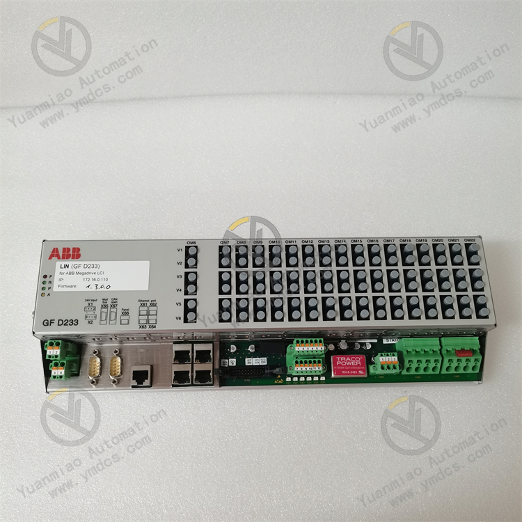
Description
Performance Characteristics
Precise Control: Utilizes advanced control algorithms and accurate measurement technologies to achieve precise control of the generator's excitation system. It ensures stable operation and optimized performance under various operating conditions, supporting multiple control modes such as constant voltage control, constant current control, and constant power factor control to meet the control needs of different generators.
Excellent Dynamic Performance: Capable of quickly responding to and adjusting excitation current during dynamic processes such as generator start-up, load changes, or grid faults, ensuring stable operation of the generator and power quality.
Strong Protection Functions: Equipped with multiple protection functions including overcurrent protection, undervoltage protection, and over-temperature protection, as well as comprehensive fault diagnosis and alarm functions to help operators quickly locate and resolve issues, ensuring the safe operation of the generator.
User-Friendly: Provides an intuitive user interface for easy monitoring, parameter adjustment, and fault diagnosis, reducing operational complexity and improving system usability.
Easy Integration: Offers standard interfaces and communication protocols for convenient integration with other automation devices and systems, enabling seamless connection and collaborative operation within existing power systems.
Technical Parameters
Operating Voltage: Referencing the related DCS-2001 distributed control system, it may use common industrial control voltages such as 24V DC or other standard voltages, but further confirmation is required.
Control Function Parameters: Enables precise voltage and current regulation, power factor control, and high control accuracy to meet the control needs of different generators under various operating conditions. Supports multiple control modes with fast dynamic response, quickly adjusting excitation current during generator start-up, load changes, or grid faults.
Protection Function Parameters: Features multiple protection functions including overcurrent protection, undervoltage protection, and over-temperature protection to effectively safeguard the generator and related equipment. Comprehensive fault diagnosis and alarm functions quickly locate faults and issue alarms for timely handling by operators.
Working Principle
I. Core Functions and Application Scenarios
- Maintain stable generator terminal voltage (constant voltage control);
- Regulate reactive power output to optimize grid power factor;
- Rapidly respond to maintain system stability during sudden load changes or grid faults;
- Provide protection and fault diagnosis for the excitation system.
- Excitation control of synchronous generators in thermal/hydropower plants;
- Generator management in industrial self-contained power stations and marine power systems;
- Power regulation for grid-level energy storage systems or renewable energy grid-connected devices.
II. Framework of Working Principle
- Signal Acquisition and Processing
Input Signals:
- Generator terminal voltage (collected via potential transformer PT);
- Generator stator current (collected via current transformer CT);
- Excitation current/voltage (collected directly from the excitation circuit);
- External setpoint signals (e.g., voltage/power settings from the host computer).
Processing Logic:
- Convert analog signals to digital signals via analog-to-digital (A/D) conversion and feed them into a microprocessor (such as a DSP or FPGA);
- Calculate key parameters such as voltage deviation, reactive power, and power factor.
- Control Algorithms and Regulation Logic
Core Control Algorithms:
- PID Control: Adjusts excitation current through proportional (P), integral (I), and derivative (D) links to eliminate voltage deviations and suppress oscillations;
- Adaptive Control: Automatically adjusts control parameters based on generator load or operating conditions to enhance dynamic response performance;
- Feedforward Control: Anticipates load change trends and adjusts excitation current in advance to reduce voltage fluctuations.
Control Mode Switching:
- Constant Voltage Mode (AVR): Maintains constant generator terminal voltage, the most commonly used mode;
- Constant Current Mode: Controls excitation current to a constant value, used for specific debugging or fault handling scenarios;
- Constant Power Factor Mode: Regulates reactive power according to grid requirements to maintain stable power factor.
- Excitation Output Control
Trigger Pulse Generation:
- Generates pulse signals based on control algorithm calculations to control the conduction angle or switching frequency of excitation power units (such as thyristor rectifier bridges or IGBT inverters);
- For example, in thyristor excitation systems, the phase angle (α) of trigger pulses is adjusted to control the rectified excitation voltage and current.
Power Amplification and Execution:
- Low-power control signals are amplified by driver circuits to drive excitation power devices (such as thyristors or IGBTs), adjusting the current in the generator's excitation winding.
- Protection and Fault Handling
Real-Time Monitoring and Protection Logic:
- Continuously monitors parameters such as voltage, current, and temperature in the excitation system. Upon detecting anomalies (e.g., overvoltage, overcurrent, overheating), it immediately triggers protection actions:
- Soft Protection: Automatically switches control modes, limits output power, or issues alarm signals;
- Hard Protection: Cuts off the excitation power supply and triggers circuit breaker tripping to prevent equipment damage.
Fault Diagnosis and Recording:
- Stores real-time data (such as waveforms and parameters) during faults for historical query to assist in locating fault causes.
- Communication and System Integration
Data Interaction:
- Exchanges data with host computers (such as DCS or SCADA systems) or other controllers (such as PLCs) via standard communication interfaces (e.g., Ethernet, RS485), including:
- Status parameters (voltage, current, power factor, etc.);
- Control commands (mode switching, parameter setting, etc.).
Protocol Compatibility:
- Supports industrial communication protocols (such as Modbus RTU/TCP, Profibus DP, IEC 61850) for seamless integration with grid automation systems.

III. Schematic Diagram of Typical Workflow
Generator terminal voltage/current → Signal acquisition module → A/D conversion → Microprocessor (control algorithm)
       ↑                          ↓
       ├────────────── Trigger pulses ──────→ Excitation power unit (thyristor/IGBT)
       └────────────── Feedback regulation ────────→ Generator excitation winding
IV. Key Technical Features (Speculative)
- Fast Dynamic Response: Capable of adjusting excitation current in milliseconds via high-speed algorithms and hardware drivers to suppress voltage fluctuations (e.g., voltage regulation accuracy ≤ ±1%) during sudden load changes (such as abrupt load application or removal).
- Redundant Design: May feature dual-processor redundancy or power supply redundancy to enhance system reliability, suitable for high-availability scenarios (such as core grid equipment).
- Wide-Range Adjustment Capability: Supports smooth adjustment of excitation current from no-load to rated load and adapts to different generator types (such as salient-pole and non-salient-pole generators).
Operation Guide
Preparations
- Familiarize with the Module: Understand basic information about the module’s functions, features, interfaces, and technical parameters by referring to relevant product manuals and technical documents.
- Hardware Inspection: Ensure the module has no physical damage, all interfaces are securely connected, and the power supply and related equipment are properly linked and operational.
Basic Operations
- Parameter Setting: Access the parameter setting interface via the module’s user interface or host computer software. Set control modes (such as constant voltage control, constant current control, constant power factor control), voltage/current setpoints, protection parameters (overcurrent protection value, undervoltage protection value, over-temperature protection value), and communication parameters according to the generator’s specific parameters and operating requirements.
- System Monitoring: Use the user interface or monitoring software to real-time monitor generator operating parameters, such as terminal voltage, stator current, excitation current/voltage, and power factor. Also, pay attention to the module’s status information, including alarm prompts and fault codes.
- Control Operations: During normal operation, switch control modes and adjust parameters via the interface or external commands as needed. For example, when grid loads change, appropriately adjust voltage or power factor setpoints to maintain stable generator operation and power quality.
Special Operations
- Generator Start-Up and Shutdown: Before starting the generator, ensure the excitation controller module is properly initialized and relevant parameters are set. During start-up, closely observe the module’s adjustment of excitation current and the establishment of generator terminal voltage, and stop the machine immediately for inspection if anomalies occur. When shutting down the generator, follow the specified procedure to first stop excitation current output, then cut off other power supplies to the generator.
- Fault Handling: When the module detects a fault, it will issue an alarm signal and display the corresponding fault code. Operators should refer to the manual or relevant materials based on the fault code to quickly locate the cause. For common faults such as overcurrent or overheating, take corresponding measures (e.g., check for overloaded loads or inadequate heat dissipation). For complex faults, contact professional technicians for maintenance.
Maintenance and Care
- Regular Inspections: Periodically check the module’s operating status, including loose hardware connections, normal operation of cooling fans, and dust accumulation on the module surface. Also, verify that parameter settings are correct and have not changed due to accidental operations or other reasons.
- Cleaning and Protection: Keep the module clean by periodically wiping the surface with a clean soft cloth. Avoid exposing the module to humid, dusty, or corrosive gas environments; if necessary, take protective measures such as installing dust covers or moisture-proof boxes.
Common Faults and Handling Methods During Operation
I. Power Supply-Related Faults
- Module Not Powered / Power Indicator Off
Possible Causes:
- External power supply not connected or voltage abnormal (e.g., input power disconnected, fuse blown).
- Loose module power interface or internal power circuit failure.
Solutions:
- Check external power input (voltage and frequency meet technical parameter requirements) and replace fuses.
- Re-plug power connection cables to ensure secure interfaces; if no response, replace the module or repair the internal power supply.
- Module Abnormalities Due to Power Voltage Fluctuations
Possible Causes:
- Unstable grid voltage or excessive interference.
- Aging or damage to power filter components.
Solutions:
- Stabilize power input with a voltage regulator or UPS.
- Inspect filter capacitors and inductors at the module’s power input; replace components or the module if bulging, burned, or damaged.
II. Excitation Regulation Abnormalities
- Generator Terminal Voltage Unestablishable / Regulation Failure
Possible Causes:
- Open circuit in the excitation current output loop (e.g., loose connections, damaged power devices).
- Faults in the voltage feedback loop (damaged sensors, poor signal cable contact).
- Incorrect parameter settings (e.g., excessively low initial excitation current, wrong control mode).
Solutions:
- Check connections from the excitation output to the generator and measure power devices (e.g., IGBTs, thyristors) for normal operation.
- Calibrate or replace voltage sensors (e.g., PT) and check feedback signal cable continuity.
- Reset factory default parameters and reconfigure, confirming the control mode (constant voltage/constant current, etc.) matches the system.
- Excessive Voltage Fluctuations or Lagging Regulation
Possible Causes:
- Feedback signal interference (unshielded cables, poor grounding).
- Unreasonable PID regulation parameter settings (unoptimized proportional coefficients, integral time, etc.).
- Too rapid generator load changes exceeding module response.
Solutions:
- Ensure feedback signal cables are individually shielded and grounded, away from strong electromagnetic interference sources.
- Re-tune PID parameters (refer to manual recommended values and optimize step-by-step).
- Limit load change amplitude or enable the module’s "load adaptive" function (if available).

III. Protection Function Activation
- Overcurrent Protection Triggered
Possible Causes:
- Excitation current exceeds the set threshold (e.g., load short circuit, internal generator fault).
- Current sensor (e.g., CT) failure or parameter setting errors.
Solutions:
- Disconnect the load, inspect the generator and circuits for short circuits, and reset protection after troubleshooting.
- Calibrate or replace current sensors and confirm overcurrent protection threshold settings (refer to generator rated parameters).
- Over-Temperature Protection Alarm
Possible Causes:
- Faulty or stopped module cooling fan.
- Poor ventilation in the installation environment or severe dust accumulation on the module surface.
- Abnormal heating of internal components (e.g., power devices).
Solutions:
- Check fan power supply and operation, clean fan blades and cooling vents, and replace fans if necessary.
- Improve installation environment ventilation and ensure module spacing meets heat dissipation requirements.
- Measure power device temperatures after shutdown; if abnormally high, repair or replace the module.
- Undervoltage/Overvoltage Protection Alarm
Possible Causes:
- Generator terminal voltage below/above set values (e.g., prime mover speed fluctuations, excitation regulation failure).
- Voltage feedback loop faults (same as "voltage unestablishable" causes).
Solutions:
- Check prime mover speed stability and manually adjust module output (e.g., temporarily switch to manual mode).
- Troubleshoot the voltage feedback loop and re-calibrate voltage setpoints after repairs.
IV. Communication-Related Faults
- Communication Interruption Between Module and Host Computer/PLC
Possible Causes:
- Disconnected communication cables, loose interfaces, or wiring errors (e.g., reversed RS485/Modbus wiring polarity).
- Inconsistent communication parameter settings (baud rate, parity bit, slave address errors).
- Damaged module communication chip or host computer interface.
Solutions:
- Inspect communication cable connections, measure cable continuity with a multimeter, and re-solder or replace cables.
- Verify communication parameters between the module and host computer for consistency (refer to manual default values).
- Test communication recovery by replacing communication interfaces (e.g., USB-to-RS485 converters) or modules.
- Data Transmission Errors or Packet Loss
Possible Causes:
- Electromagnetic interference in communication lines (e.g., parallel routing with power cables).
- Excessive communication speed causing signal attenuation.
Solutions:
- Use shielded twisted-pair cables, route communication and power cables separately, and add termination resistors (e.g., in Modbus networks).
- Reduce communication baud rate or install repeaters to extend communication distance.
V. Other Common Faults
- Module Alarm Light On Without Clear Fault Code
Possible Causes:
- Abnormal internal software operation or program errors.
- Non-critical component failures (e.g., standby sensor anomalies).
Solutions:
- Attempt to power-cycle the module to clear temporary faults.
- Connect debugging software to read detailed logs and troubleshoot hidden issues as prompted.
- Manual/Automatic Mode Switching Failure
Possible Causes:
- Damaged mode switch button/switch.
- Software permission restrictions or program logic errors.
Solutions:
- Replace physical buttons or inspect switch wiring.
- Confirm operation permissions via the host computer and restart the module or refresh firmware.