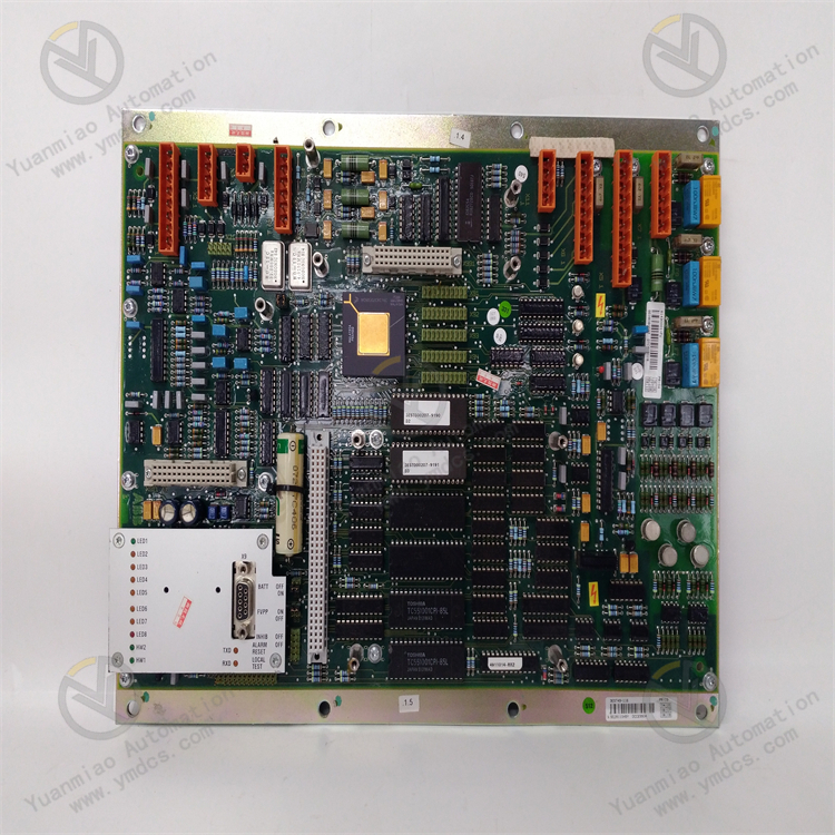
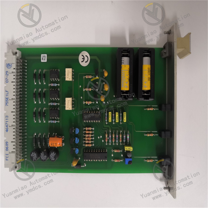
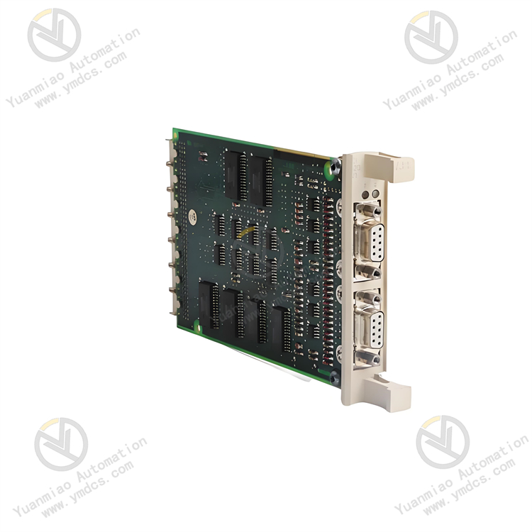
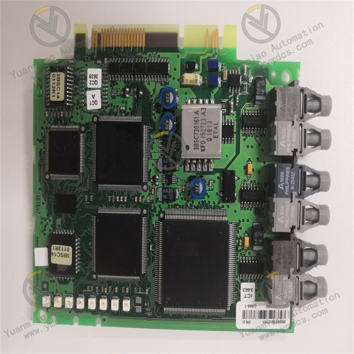
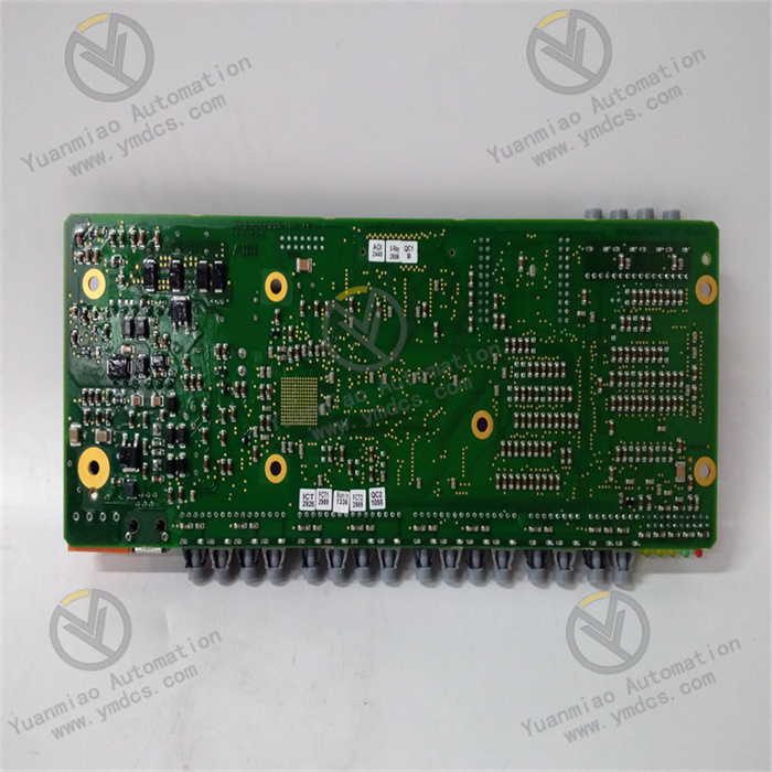
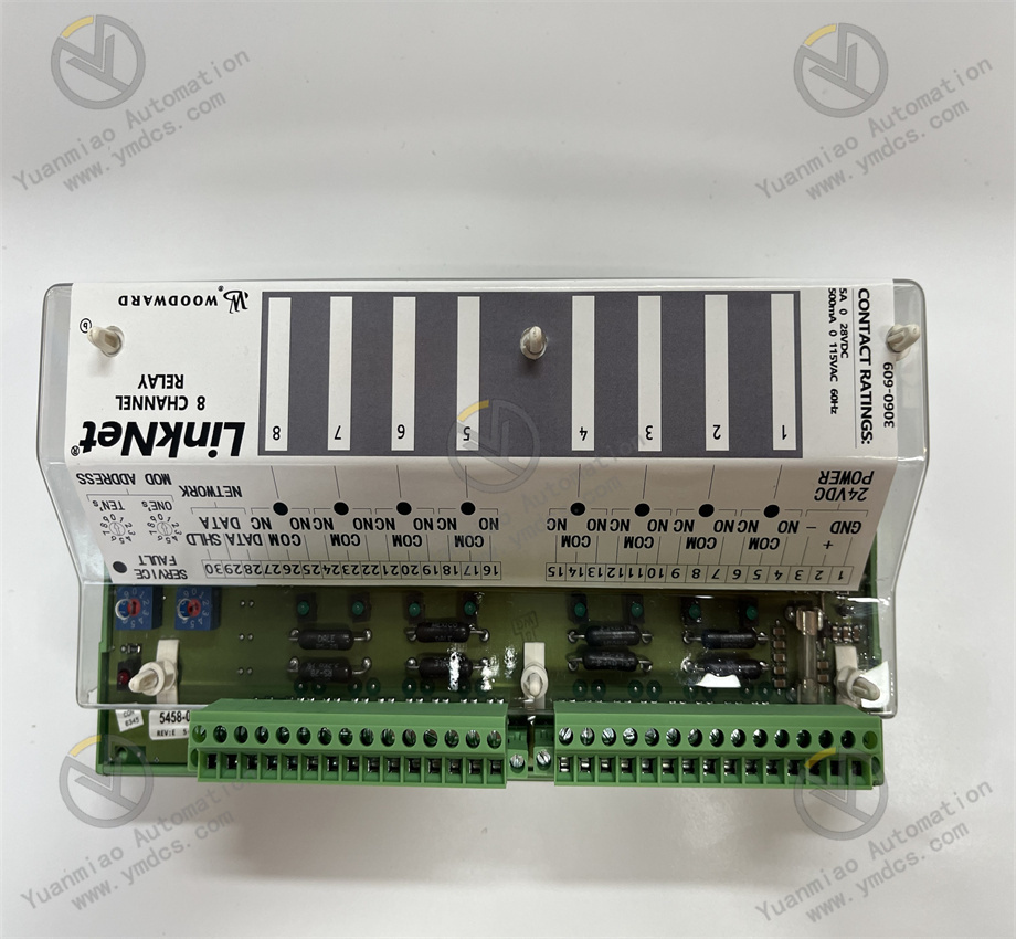
Description
The WOODWARD 9905 - 792 is a digital speed control module, mainly used for precisely adjusting the speeds of engines and motors in various industrial applications.
Features Precise Control: Controlled by a microprocessor and adopting advanced digital control technology and algorithms, it can precisely adjust the motor speed with high control accuracy. For example, some data shows that the control accuracy can reach ±1%. Multiple Feedback Modes: It supports multiple speed control modes such as tachometer feedback, current feedback, and voltage feedback, and can be flexibly selected according to different application scenarios and requirements to achieve the best control effect. Multiple Protection Functions: It has multiple protection functions such as overvoltage, overcurrent, undervoltage, short circuit, and grounding fault, which can effectively protect the motor and the controller itself from damage and improve the reliability and stability of the system. Communication Function: It usually has an RS - 485 communication interface and supports the Modbus communication protocol, which can be conveniently connected and communicated with other devices or automation systems to achieve remote monitoring and control. Adaptability to Harsh Environments: With a compact and sturdy design, it has a high protection level, such as IP54 or IP65. It can withstand harsh conditions such as dust and water splashing in the industrial environment and can work stably within a temperature range from - 20℃ to + 50℃ or even wider.
Technical Parameters Power Supply Voltage: 24V DC. Some data shows that the input voltage range is 24 - 48V DC or 24V DC to 250V AC. Power Consumption: Less than 5 watts. Input Channels: Including 1 speed sensor input, 2 analog inputs (for feedback signals), and up to 4 digital inputs. Output Channels: There are 2 configurable outputs (for motor control) and 1 relay output (for alarm signals).
Application Scenarios Power Industry: In devices such as generators and motors, it is used to precisely control the speed to ensure the stability and quality of power output. For example, in a power plant, it can control the engine speed of the generator set to ensure the stability of the power generation frequency. Industrial Manufacturing: Suitable for various production equipment that requires precise speed control, such as fans, pumps, compressors, etc. By precisely adjusting the speed of the equipment, it can improve production efficiency, reduce energy consumption, and ensure the safe operation of the equipment. For example, in chemical production, it controls the speed of the pump to precisely convey various chemical raw materials. Transportation: In the transportation fields such as ships and railways, it can be used to control the speeds of engines or motors to achieve the speed adjustment and power control of vehicles or ships. For example, in the propulsion system of a ship, it controls the engine speed to adapt to different navigation conditions. Other Fields: It can also be applied to fields that require precise control of the speeds of motors or engines, such as HVAC systems and mining machinery. For example, in the HVAC system of a large shopping mall, it controls the speed of the fan to adjust the air flow and temperature.

The WOODWARD 9905 - 792 is a digital speed control board. The following are some common troubleshooting methods:
1. Power Supply Fault
Fault Phenomenon: The control board has no display or cannot start normally.
Inspection Method: Use a multimeter to measure the input power supply voltage to ensure that it is within the range of 24 - 48V DC. Check whether the power supply connection cable is loose, damaged, or poorly connected. If there is a problem, repair or replace the connection cable. If the power supply voltage is normal but the control board still does not respond, it is likely that the power module inside the control board has a fault, and professional maintenance personnel need to be contacted for inspection or replacement.
2. Inaccurate Speed Control
Fault Phenomenon: The actual motor speed does not match the set speed, or the speed fluctuates greatly.
Inspection Method: First, confirm whether the speed sensor is working properly. Check whether the installation position of the sensor is correct, whether there is looseness or damage, and whether the connection cable is in good condition. Then check whether the speed control mode setting is correct. For example, whether a suitable feedback mode (such as tachometer feedback, current feedback, or voltage feedback) is selected. Also, check whether the motor load is stable, and whether there are overload or sudden change situations, because changes in the load may affect the accuracy of speed control. If the above inspections are all normal, it is likely that the parameter settings of the control board are unreasonable, and relevant parameters such as proportional, integral, and differential parameters need to be adjusted according to the actual situation to optimize the control performance.
3. Communication Fault
Fault Phenomenon: The control board cannot communicate normally with other devices (such as the upper computer, PLC, etc.).
Inspection Method: Confirm whether the connection cable of the communication interface (such as RS - 485) is correctly connected and undamaged, and whether the interface is in good contact. Check whether the communication protocol settings are consistent, including parameters such as baud rate, data bits, stop bits, and parity bits, to ensure that the settings of the control board match those of the communication object. Check the device address settings of the control board and the communication object to see if there is an address conflict. If the communication line and settings are all normal, you can try to send some simple test commands to check whether the communication is normal. If communication is still not possible, it is likely that the communication module of the control board has a fault, and maintenance or replacement is required.
4. Triggering of Protection Functions
Fault Phenomenon: The control board displays a fault code or the indicator light turns on, indicating that faults such as overvoltage, overcurrent, undervoltage, short circuit, or grounding fault have occurred.
Inspection Method: Determine the specific type of protection according to the fault code displayed on the control board or the information of the indicator light. For overvoltage and undervoltage faults, use a multimeter to measure the input power supply voltage to see if it exceeds the normal working range. For overcurrent faults, check whether there are short circuit or grounding situations in the motor and the connection cable, and whether the motor load is too large. For short circuit and grounding faults, use an insulation resistance tester to check the insulation resistance of the motor, cable, and related equipment, and find possible short circuit points or grounding points. If it is found that the fault is caused by external equipment, after repairing or replacing the faulty equipment, the control board needs to be reset to clear the fault alarm and restore normal operation.
5. Abnormal Output
Fault Phenomenon: The output signal of the control board (such as the signal for motor control) is abnormal, resulting in the motor not being able to operate normally or operating abnormally.
Inspection Method: Check whether the settings of the output channel are correct, including parameters such as output type and range. Use an oscilloscope or multimeter to measure parameters such as the amplitude and frequency of the output signal to see if they match the set values. If the output signal is normal but the motor still cannot operate normally, check whether the connected equipment such as the motor driver or relay is working properly and whether there is any damage or fault. If the output signal is abnormal, it is likely that there is a problem with the output circuit of the control board, and professional personnel need to be contacted for maintenance.