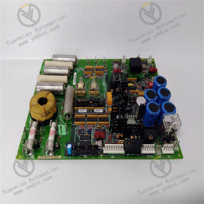
GE IS200TRPAH2AHE | Exciter Power Supply Module

GE IS200TRPAH2AHE | Exciter Power Supply Module

Brand: General Electric

Product ID: IS200TRPAH2AHE

Condition: New / used

Terms of payment: Paypal、T/T 、Western Union

Category:

Description

GE IS200TRPAH2AHE

I. Overview


The GE IS200TRPAH2AHE is a high-end trip logic module developed for the Mark VIe industrial safety control system. Its core positioning is to provide an integrated solution of "safety interlock judgment + emergency shutdown control" for critical industrial equipment (such as gas turbines, steam turbines, and large compressors), and it undertakes the core role of "fault signal collection + logic calculation + trip command execution". Breaking the limitations of traditional discrete trip control, this module realizes real-time monitoring, priority judgment, and rapid intervention of multi-dimensional fault signals through highly integrated hardware logic and software configuration functions. It is widely used in scenarios with strict requirements for safety response speed and logic reliability, including steam turbine protection systems in power plants, safety interlocks for petrochemical reactors, emergency shutdown control for metallurgical rolling mills, and pressure protection for natural gas transmission pipelines.


The module adopts a "compact hardware architecture + triple redundant logic design", is suitable for standard rack installation of the GE Mark VIe system, and can seamlessly collaborate with components such as TRPG trip terminal boards and TMR (Triple Modular Redundancy) input modules. Its core advantages lie in the technical integration of "millisecond-level response" and "high safety redundancy": it has a built-in high-speed logic operation chip (response time ≤ 5ms) to ensure that trip actions are triggered within 100ms after a fault occurs; at the same time, it is equipped with a triple redundant power supply, triple redundant communication links, and a "two-out-of-three" voting logic circuit, completely eliminating misoperations or refusal to operate caused by single-point faults. With an operating temperature range of -30°C to +65°C, it can resist strong electromagnetic interference (such as inverter harmonics), voltage fluctuations, and dust erosion in industrial sites, building a "in-depth defense" safety protection system for complex industrial systems.


II. Technical Parameters


Parameter CategorySpecific SpecificationsRemarks
Core Control ParametersFault Input Channels: 16 digital input channels (dry contact/wet contact optional)The voltage range of wet contacts is 24V DC ±15%, supporting the collection of multiple types of fault signals such as sensor faults, over-temperature, and over-pressure

Trip Output Channels: 8 relay output channels (250V AC/30V DC, 5A)Each output channel is independently configured, supporting the control of actuators such as emergency shutdown valves and fuel cut-off valves

Logic Operation Speed: ≤ 5msQuickly processes multi-dimensional fault signals to ensure timely issuance of trip commands

Trip Response Time: ≤ 100ms (from fault detection to output action)Meets the emergency protection needs of equipment such as steam turbines and reactors
Redundancy CharacteristicsPower Supply Redundancy: 3 independent 24V DC inputs (supporting 1+1+1 redundancy)A single power supply fault does not affect the module's operation, ensuring power supply continuity

Communication Redundancy: 2 Ethernet (Profinet IRT) + 2 RS485 (Modbus RTU)Ethernet supports redundant link switching (switching time ≤ 10ms), and RS485 is used for local debugging and monitoring

Logic Redundancy: "Two-out-of-three" voting logicFor key fault signals (such as steam turbine overspeed), three input signals are used for voting judgment to avoid single-point false alarms
Electrical CharacteristicsInput Impedance: ≥ 10kΩ (digital input)Reduces the load of external signal sources and avoids signal attenuation

Output Load Capacity: 0-800Ω (relay output)Can directly drive medium and large actuators without additional intermediate relays

Overvoltage Protection: Automatically cuts off when input voltage ≥ 36V DCPrevents damage to internal circuits caused by external power supply faults

Surge Immunity: ±8kV (line-to-ground), ±4kV (line-to-line)Complies with IEC 61000-4-5 standard, resisting power grid surge impacts
Physical & Environmental ParametersInstallation Method: Standard 35mm DIN rail installation / Mark VIe rack installationAdapts to the standardized layout of industrial control cabinets and supports close cascading of multiple modules

Dimensions: 180mm × 120mm × 60mm (Length × Width × Height)Compact design, saving control cabinet space

Weight: Approximately 500gLightweight structure, facilitating installation in high-altitude and vibrating environments

Operating Temperature: -30°C to +65°C, Storage Temperature: -40°C to +85°CWide-temperature design, adapting to extreme environments such as outdoor cold areas and high-temperature workshops

Protection Rating: IP20 (module itself), IP65 (optional waterproof housing)The module itself is suitable for installation inside control cabinets; the waterproof housing is applicable to humid and dusty on-site environments


III. Functional Features


1. Multi-Dimensional Fault Monitoring and Priority Logic Control

The module has the capability of "16 fault input channels + custom logic configuration", which can simultaneously collect multiple types of fault signals such as equipment over-temperature, over-pressure, excessive vibration, and sensor disconnection. It can configure priority judgment logic (e.g., "steam turbine overspeed" has higher priority than "low lubricating oil pressure") through GE Control Studio software. For example, in a gas turbine protection system, when both "rotational speed exceeding 115% of rated value" (level 1 fault) and "cooling water temperature exceeding 50°C" (level 2 fault) are detected simultaneously, the module will prioritize the level 1 protection action of "cutting off fuel supply + triggering emergency shutdown", and handle the level 2 fault only after the equipment is safely shut down, avoiding logic confusion under multiple faults. At the same time, it supports delayed filtering of fault signals (configurable from 0-1000ms), which effectively filters out transient false alarm signals caused by electromagnetic interference and improves the accuracy of logic judgment.


2. Triple Redundancy Architecture and "Two-out-of-Three" Safety Logic

It adopts a full-link triple redundancy design of "power supply - communication - logic": 3 independent 24V DC power inputs are automatically switched through a redundant power management chip to ensure uninterrupted operation of the module in case of a single power supply fault; 2 Ethernet redundant links support the Profinet IRT protocol, and the backup link switches within ≤ 10ms when the main link fails, ensuring real-time data interaction with the Mark VIe system CPU; the core logic circuit adopts a "two-out-of-three" voting mechanism, which conducts majority voting on key fault inputs (such as 3 independent speed sensor signals) and only executes the trip action when 2 or more signals trigger a fault, completely eliminating false shutdowns caused by single-point sensor faults. For example, in steam turbine speed protection, if one speed sensor falsely reports "overspeed", the module will ignore the signal and only trigger a shutdown when 2 or more sensors confirm overspeed, greatly improving the operational reliability of the system.


3. Millisecond-Level Response and Visual Fault Tracing

With a built-in high-speed FPGA logic operation chip, the full-process response time from fault signal collection, logic judgment to trip command output is ≤ 100ms, which is 50% faster than traditional PLC-based trip systems, and can effectively prevent the expansion of malignant accidents such as steam turbine overspeed and reactor over-pressure. At the same time, the module supports the "fault event recording" function, which can store 1000 pieces of historical fault information (including "fault type + occurrence time + trigger channel + handling action"). Through GE Proficy Historian software, the fault timing curve can be queried remotely, facilitating maintenance personnel to trace the cause of the accident. For example, after an explosion accident of a chemical reactor, the timing data of "pressure over-limit → rapid temperature rise → trip trigger" recorded by the module can be used to quickly locate the source of the accident (such as jamming of the feed valve) and provide a basis for subsequent improvements.


4. Flexible System Compatibility and Expansion Capability

It is deeply compatible with the GE Mark VIe control system, can be directly connected to the system's TMR architecture, and realizes plug-and-play with components such as TRPG trip terminal boards and TTUR speed monitoring modules without additional protocol conversion equipment. At the same time, it supports the integration of third-party equipment, and can communicate with systems such as Siemens S7-1500 PLC and Rockwell ControlLogix through the Modbus RTU protocol, uploading data such as fault status and trip actions to third-party monitoring platforms. In addition, it supports modular expansion: 16-channel digital input modules (such as IS200DIAH1A) can be expanded through the CANopen interface, and the maximum number of input channels can be expanded to 64, adapting to centralized protection scenarios for multiple equipment in large petrochemical parks and power plants, and significantly reducing system construction costs.


5. Full-Lifecycle Safety Management and Maintenance Convenience

The maintenance design focuses on "balancing safety and efficiency": it supports online firmware upgrades (completed remotely via Ethernet) to update logic algorithms without powering off; it has a built-in self-diagnosis function that continuously monitors the status of the module's power supply, communication interface, and relay contacts. When faults such as "relay contact adhesion" and "communication link interruption" are detected, it immediately triggers local sound and light alarms (flashing red LED + intermittent buzzer alarm) and sends fault codes (such as "E03 - Relay Output Fault") to the upper computer, facilitating maintenance personnel to conduct timely troubleshooting. Meanwhile, it adopts a pluggable terminal block design, so there is no need to disconnect wires when replacing the module. With clear terminal labels (such as "IN1 - Speed Over-Temperature", "OUT1 - Fuel Cut-Off Valve"), maintenance personnel can replace a faulty module in only 5 minutes, significantly reducing system downtime.


IV. Common Faults and Solutions


Fault PhenomenonPossible CausesSolutions
1. No response after the module is powered on, and the power indicator is off1. Redundant power supplies are not fully connected or a certain power supply is open-circuited; 2. Loose power terminals or incorrect wiring; 3. Damaged internal redundant power management chip; 4. Burned fuse1. Use a multimeter to measure the 3-channel 24V DC power input to ensure all are normally powered, and repair the open-circuited power line; 2. Check the power terminals (such as "PWR1+", "PWR2-"), re-plug and fasten them to ensure correct positive and negative wiring; 3. If there is still no response when the power supply is normal, contact GE-authorized maintenance personnel to inspect the redundant power management chip (such as TI TPS7A4700) and replace the damaged component; 4. Check the internal fuse of the module (usually 2A/250V), and replace it with a fuse of the same specification if it is burned (GE original accessories are recommended)
2. Fault signal is triggered but no trip action is executed1. Incorrect trip logic configuration (such as "two-out-of-three" logic not enabled, excessively low priority setting); 2. Faulty output relay (contact adhesion or burned coil); 3. Open-circuited actuator line or excessive load; 4. Communication fault between the module and the TRPG terminal board1. Check the trip logic configuration through GE Control Studio software, enable the "two-out-of-three" voting function, and increase the priority of key faults (e.g., set to level 1); 2. Power off the module, use a multimeter to measure the on-off status of the relay contacts (normal on-resistance ≤ 0.5Ω, off-resistance is infinite); if the contacts are adhered, polish them with fine sandpaper; if the coil is burned, replace the relay (such as Omron G5LE-14); 3. Check the on-off status of the actuator line and the load current to ensure the load ≤ 5A, repair the open-circuit point, and add an intermediate relay for expansion if the load is excessive; 4. Check the communication line between the module and the TRPG terminal board, re-plug the Ethernet/RS485 connector, and restart the communication link
3. The module falsely triggers a trip and shuts down without a fault signal1. The fault input channel is affected by electromagnetic interference, generating transient false alarm signals; 2. Excessively short logic filtering time (e.g., 0ms); 3. Sensor fault causing false fault signals; 4. "Two-out-of-three" logic not enabled, leading to false triggering by a single-point signal1. Replace the signal wire of the fault input channel with a double-shielded twisted pair, ground the shield at one end (near the module), and keep it away from strong interference sources such as inverters and motors; 2. Increase the logic filtering time (recommended to set 50-100ms) in GE Control Studio software to filter out transient false alarm signals; 3. Use a high-precision calibrator (such as FLUKE 754) to test the sensor and replace the faulty sensor; 4. Enable the "two-out-of-three" voting logic, and configure 3 redundant sensors for key fault inputs (such as speed and pressure) to avoid false triggering by single-point signals
4. Redundant communication link switching fails, and data transmission is interrupted1. Inconsistent communication parameter configurations (such as IP address, baud rate, slave address); 2. Poor contact or open circuit of the redundant communication line; 3. Damaged communication interface chip; 4. Fault of the Mark VIe system CPU1. Verify the communication parameters between the module and the Mark VIe system to ensure the IP address is in the same network segment, and the baud rate (e.g., 115200bps) and slave address are consistent; 2. Use a network cable tester to check the Ethernet line, use a multimeter to measure the on-off status of the RS485 line, re-plug and fasten the connector, and repair the open-circuit point; 3. Connect the communication cable to the backup communication interface; if communication is normal, it indicates that the original interface is damaged, and the communication chip (such as MAX485) needs to be replaced; 4. Restart the Mark VIe system CPU, check the system operation status, and eliminate CPU faults
5. The module self-diagnosis alarms, displaying "Relay Output Fault"1. Oxidized or burned relay contacts; 2. Short circuit or overload of the output circuit; 3. Damaged relay driver chip; 4. False alarm of the self-diagnosis circuit (outdated firmware version)1. Power off the module, disassemble the relay housing, and polish the oxidized contacts with fine sandpaper; if burned, replace the relay with the same model; 2. Check the load of the output circuit, use a multimeter to measure whether there is a short circuit, ensure the load current ≤ 5A, and repair the short-circuit point; 3. Test the relay driver chip (such as ULN2804); if the output voltage is abnormal, replace the driver chip; 4. Remotely upgrade the module firmware to the latest version (e.g., V2.5) via Ethernet to eliminate the false alarm bug of the self-diagnosis circuit

contact us