Description
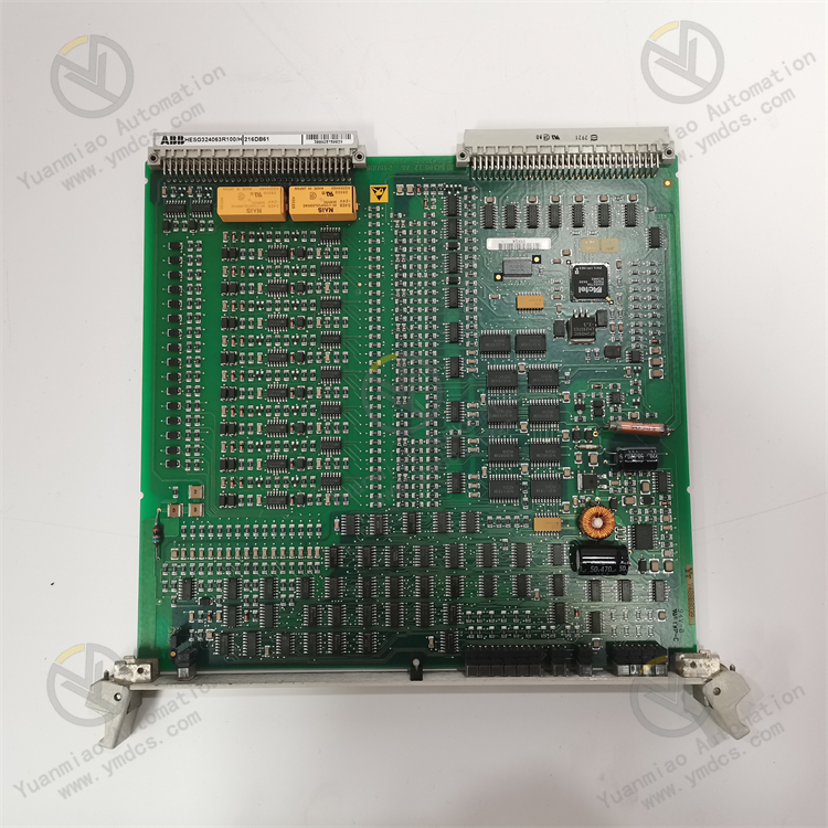
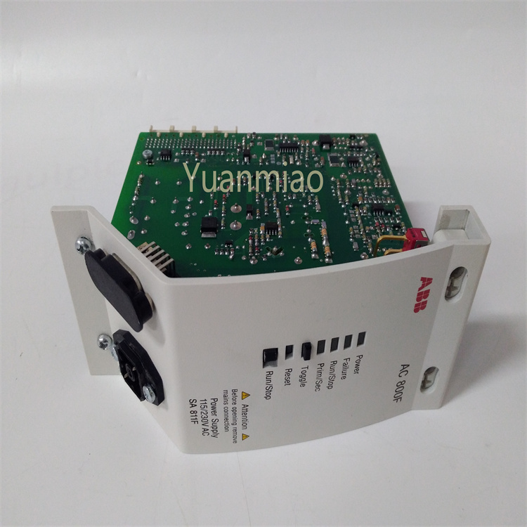
ABB CI853K01 3BSE018103R1
Functional Features
I. Module Positioning and Application Scenarios
- Positioning: A communication interface module belonging to ABB's AC 800M series, primarily used in industrial automation control systems to enable data interaction and communication between different devices and systems.
- Typical Application Scenarios:
- Connecting PLC/DCS systems with field sensors, actuators, variable frequency drives, and other devices.
- Supporting integration and data transmission for industrial networks (e.g., PROFIBUS DP, Modbus).
- Suitable for high-reliability industrial environments such as power, chemical, metallurgy, and manufacturing.
II. Core Functions
- Multi-Protocol Communication Support
- Supports PROFIBUS DP V1 master/slave modes, enabling connection to intelligent devices (e.g., transmitters, drives) in PROFIBUS networks.
- Compatible with Modbus RTU/ASCII protocols for easy integration of third-party devices (e.g., instruments, controllers).
- Supports custom communication protocols (requires software configuration), offering high flexibility.
- High-Speed Data Processing and Transmission
- Utilizes a high-performance processor to enable real-time data exchange, with a maximum communication rate of 12 Mbps (PROFIBUS).
- Features data caching and preprocessing to reduce the load on the main controller.
- Redundancy and Reliability Design
- Supports hot-swapping, allowing module replacement without system shutdown to enhance availability.
- Built-in diagnostics for real-time monitoring of communication status, power failures, bus errors, etc., with alarms via LED indicators or system logs.
- Meets industrial-grade protection standards (e.g., EMI resistance, wide temperature operation) for harsh environments.
- Flexible Configuration and Programming
- Configures parameters and designs network topology via ABB Control Builder M software, supporting graphical interface operations.
- Compatible with ABB's programming framework (e.g., IEC 61131-3 standard) for collaborative operation with other AC 800M modules.
III. Physical and Electrical Characteristics
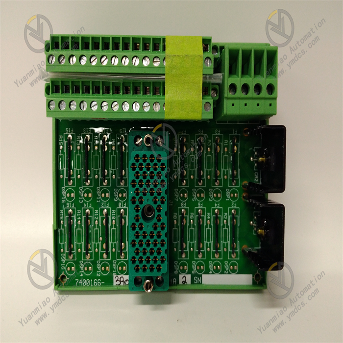
- Interface Types:
- PROFIBUS interface: DB9 connector supporting redundant bus connections.
- Local interface: Connects to the AC 800M controller backplane for high-speed data transmission.
- Power Supply: Backplane-powered (24 V DC) with low power consumption (typically ~5 W).
- Mechanical Dimensions: Compact design for standard DIN rail mounting, saving control cabinet space.
IV. Compatibility and Expandability
- System Compatibility:
- Seamlessly integrates with ABB's Industrial IT system, supporting docking with OPC servers and SCADA software (e.g., ABB Freelance).
- Compatible with third-party HMI devices for data visualization and monitoring.
- Expandability:
- Multiple CI853K01 modules can be expanded in a single AC 800M system to support parallel operation of multiple networks.
- Extendable to other industrial networks (e.g., Ethernet/IP, PROFINET) via gateway modules.
V. Summary of Advantages
- High Reliability: Industrial-grade design suitable for 24/7 critical operations.
- Strong Compatibility: Supports multiple mainstream industrial protocols for easy system integration and device expansion.
- Easy Maintenance: Hot-swapping and diagnostic functions reduce maintenance costs and downtime.
- Flexibility: Software-configurable to adapt to different communication needs, minimizing hardware customization costs.
Technical Parameters
I. Electrical Parameters
- Power Voltage: 24VDC (±10%)
- Power Consumption: Typical 100mA, maximum 150mA
- Input/Output Isolation:
- Isolation between communication interface and logic circuit
- Isolation voltage: 500V AC (1 minute)
- EMC Compatibility: Complies with EN 61000-6-2 (industrial environment) and EN 61000-6-4 (emission) standards.
II. Communication Parameters
- Communication Protocols:
- Primary protocol: Com II (ABB internal protocol)
- Secondary protocol: Modbus RTU
- Communication Ports: 2 RS232-C ports (independent channels)
- Transmission Rate: 75–19200b/s (configurable)
- Maximum Stations per Channel: Up to 32 slaves
- Communication Distance:
- RS232: Maximum 15 meters (standard)
- Extendable to 1200 meters via RS232/RS485 converter (RS485 mode)
- Bit Error Rate: <10⁻⁹ (typical)
III. Mechanical Parameters
- Dimensions (W×H×D): 59mm × 185mm × 127.5mm
- Weight: ~700g (including base)
- Mounting Method: Standard DIN rail mounting
- Housing Material: Flame-retardant plastic compliant with UL 94 V-0 standard.
IV. Environmental Parameters
- Operating Temperature: +5°C to +55°C
- Storage Temperature: -40°C to +70°C
- Relative Humidity: 5–95% (non-condensing)
- Protection Level: IP20 (front panel)
- Vibration Resistance: Complies with IEC 60068-2-6 (10–57Hz, 0.75mm amplitude)
- Shock Resistance: Complies with IEC 60068-2-27 (15g, 6ms)
V. Functional Parameters
- Processing Capacity:
- Maximum data throughput: 1000 I/O points per second
- Response time: <10ms (typical)
- Diagnostic Functions:
- Power failure detection
- Communication link status monitoring
- Internal hardware fault diagnosis
- Redundancy Support:
- Supports dual-module redundancy configuration
- Automatic switchover time <50ms
Operation Guide
Hardware Installation
- Ensure relevant power is cut off before installation to avoid electric shock or equipment damage.
- Install the CI853K01 module correctly on the DIN rail using sliding and locking mechanisms as per device specifications and installation manual.
- Connect required communication cables (e.g., RS-232C), ensuring secure connections to prevent communication failures due to looseness. For hot-swappable CI853 modules, while live insertion/removal is supported, perform installation/removal under power-off conditions whenever possible to reduce potential risks.
Protocol Configuration
- ComII Protocol Configuration:
- If using ComII, set communication parameters (baud rate, data bits, stop bits, parity, etc.) in the relevant controller or device to match those of the CI853K01 module and the peer communication device. The CI853 supports master/slave modes in ComII; configure the module as master or slave based on actual application needs.
- Modbus RTU Protocol Configuration:
- For Modbus RTU, configure Modbus functions on the AC 800M and CI853 COM ports. Set Modbus RTU parameters (baud rate, data bits, stop bits, parity, etc.). The CI853 only supports Modbus RTU master mode; set it as the master station and configure slave device addresses and other related parameters.
Software Setup and Monitoring
- Use programming software or configuration tools (e.g., ABB's programming software for AC 800M controllers) to connect to the controller and CI853K01 module.
- Perform module initialization in the software, including confirming and modifying module addresses, communication parameters, etc.
- Monitor the CI853K01 module's operating status via software (e.g., check communication indicator lights, data transmission statistics) to determine normal operation. In case of faults, troubleshoot based on error codes or alarm messages prompted by the software.
Routine Maintenance
- Regularly inspect the module's appearance for signs of overheating, burning, or damage.
- Clean dust and dirt from the module surface to maintain good heat dissipation and operating environment.
- Check communication cable connections for looseness or damage.
- Monitor the module's operating status; promptly investigate and resolve abnormal issues such as communication interruptions or data errors.

Common Issues and Solutions in the Operation Guide
I. Communication Connection Issues
- Module Fails to Establish Communication with PROFIBUS Slave
- Possible Causes:
- Incorrect hardware connections (e.g., disconnected cables, unenabled terminator resistors).
- Mismatched baud rate or slave address settings with the slave device.
- Module power failure or unstable voltage.
- Electromagnetic interference on the PROFIBUS bus.
- Solutions:
- Check hardware connections: Ensure bus cables are securely connected, and terminator resistors (typically 90Ω, with a switch on the module side or bus connector) are inserted for terminal devices. Measure bus voltage with a multimeter (normal: 9–32V DC).
- Verify parameter settings: Use ABB Control Builder M to check the module’s baud rate (e.g., 9600bps, 1.5Mbps) and slave address (0–126) for consistency with the slave. Restart the module or slave device to ensure parameters take effect.
- Eliminate interference: Keep bus cables away from strong electromagnetic sources (e.g., motors, inverters), and use shielded twisted-pair cables with reliable grounding.
- Abnormal or Dropped Communication Data
- Possible Causes:
- Excessive bus load (exceeding the module’s maximum supported slave count).
- Incompatible communication protocols (e.g., module configured for DP-V0, slave using DP-V1).
- Cable length exceeding the bus maximum (related to baud rate; e.g., ~200 meters at 1.5Mbps).
- Solutions:
- Optimize bus configuration: Check the module’s maximum supported slaves (CI853K01 typically supports ≤125 slaves) and reduce redundant nodes. Enable the watchdog timer via software and set a reasonable timeout (e.g., 500ms).
- Adjust protocol version: Confirm the module’s protocol version in Control Builder M and update slave firmware or reconfigure as necessary.
- Extend bus distance: Add a PROFIBUS repeater or reduce the baud rate to increase distance (e.g., ~1200 meters at 9600bps).
II. Abnormal Module Status Indicators
- Power Indicator (PWR) Off
- Possible Causes:
- Power not connected or faulty power cable.
- Internal fuse blown.
- Solutions:
- Check power input (24V DC) and replace power cables or modules.
- If field fuse replacement is supported, inspect and replace the fuse after powering off (refer to manual disassembly steps).
- Communication Status Light (COM) Flashing or Off
- Possible Causes:
- Incorrect communication parameters (e.g., address conflict, baud rate mismatch).
- Faulty or unpowered slave device.
- Solutions:
- Use diagnostic tools (e.g., ABB’s Online Diagnostics) to scan the bus and check slave status.
- Disconnect slaves one by one to identify if a single faulty slave causes bus failure.
- Error Indicator (ERR) Constantly On
- Possible Causes:
- Module hardware failure (e.g., damaged chip, loose interface).
- Software configuration error (e.g., missing GSD file for slave device).
- Solutions:
- Reinsert the module to ensure good contact with the backplane bus.
- Check if the slave’s GSD file is loaded in Control Builder M and redownload the configuration program. If issues persist, contact ABB technical support for module replacement.
III. Software Configuration and Programming Issues
- Module Unrecognized in Software
- Possible Causes:
- Incorrect hardware driver installed or outdated firmware.
- Backplane bus communication failure (e.g., damaged backplane module).
- Solutions:
- Ensure the latest hardware support package (HSP) for ABB AC 800M is installed and update the module firmware.
- Replace the backplane slot or module to test for hardware compatibility issues.
- Incorrect Data Mapping (Abnormal I/O Data)Possible Causes:
- Incorrect I/O address configuration.
- Mismatched slave data format with module configuration (e.g., byte order, data type).
- Solutions:
- Check I/O address allocation in Control Builder M for consistency with slave device register addresses.
- Use symbol tables to define data points and avoid manual address input errors. If supported, enable automatic data mapping via GSD files for structure matching.