Description
1. Product Overview
Full Model: IS200TVBAH2ABB
Manufacturer: GE General Electric
Product Series: Mark VIe Speedtronic Turbine Control System Vibration Monitoring Terminal Board Series
Product Name: TVBA Unit Vibration Input Terminal Board, Shaft / Bearing Vibration Signal Conditioning Board
Product Positioning
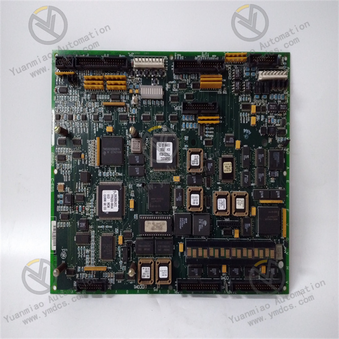
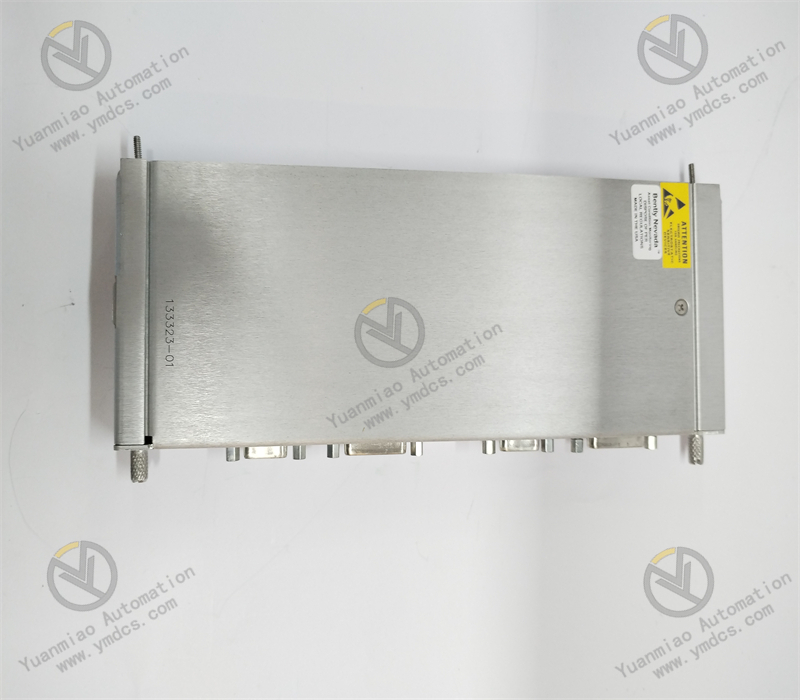
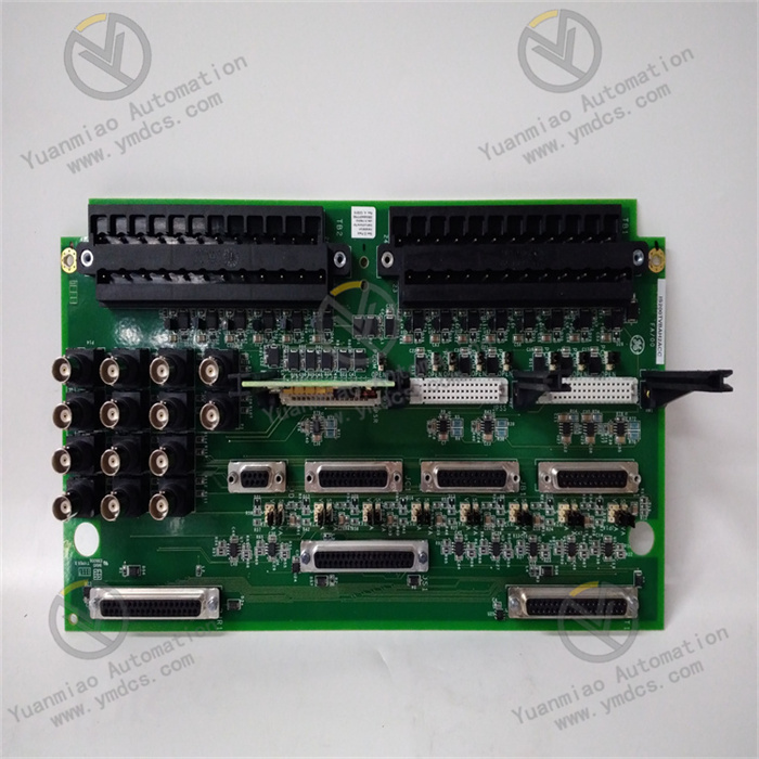
IS200TVBAH2ABB is a high-precision vibration acquisition terminal board dedicated to the GE Mark VIe turbine control system. It serves as a specialized hardware unit for front-end acquisition, shielding conditioning and signal arrangement of shaft vibration, bearing vibration and casing vibration signals. Acting as the core transfer carrier between vibration sensors and back-end main acquisition modules, the board is responsible for termination, filtering, isolation, impedance matching and signal routing of analog vibration signals from turbine units. It is a critical front-end device for unit vibration monitoring, fault early warning and shaft safety protection. Adopting power plant grade high-precision signal conditioning technology and full-range electromagnetic shielding design, it reliably operates under harsh on-site conditions featuring intensive electromagnetic interference, high temperature, mechanical vibration, dust and humidity. It ensures high accuracy, stability and repeatability of vibration signal acquisition. As an indispensable terminal board for unit condition monitoring and equipment fault diagnosis within the Mark VIe system, it is widely applied in gas-steam combined cycle power plants, thermal power turbine units, large industrial power turbines and compressor units for new unit matching, system retrofits and spare part replacement.
Core Functions
The module implements five major functions: isolated vibration signal acquisition, hardware filtering and noise reduction, impedance matching calibration, standardized shielding grounding management and multi-channel vibration signal routing transmission. It is compatible with velocity, piezoelectric and magnetoelectric vibration probes, and continuously collects key equipment condition signals including bearing vibration, shaft vibration and casing vibration. Equipped with built-in multi-stage hardware filtering and signal isolation circuits, the board suppresses on-site electromagnetic noise, mechanical disturbance and line coupling interference. It shapes, amplifies, denoises and calibrates raw weak vibration signals, and outputs standardized clean vibration signals to back-end main acquisition modules in orderly routing. Meanwhile, it standardizes single-point grounding for all vibration cable shields to eliminate signal drift, jitter, distortion and noise rise. It delivers accurate and reliable front-end signal support for vibration trend analysis, equipment fault diagnosis, shaft anomaly early warning and vibration trip protection, establishing a solid safety monitoring barrier for unit equipment conditions.
Compatible Systems
Fully compatible with the complete GE Mark VIe Speedtronic turbine control system, supporting simplex, dual redundant and TMR Triple Modular Redundant control architectures for gas turbines, steam turbines, industrial drive turbines and large high-speed compressor main control systems. It seamlessly cooperates with system vibration acquisition modules, analog processing boards, main CPU modules, redundant power units and signal terminal backplanes. Natively compliant with Mark VIe backplane bus protocol, signal configuration logic and cabinet installation specifications. Backward-compatible plug-and-play replacement is available without modification of system programs, control logic and primary wiring. Direct in-situ installation restores full vibration monitoring functionality. It covers all engineering scenarios including new unit commissioning, replacement of aged boards, vibration monitoring system optimization and expansion of unit condition monitoring.
Application Scenarios
Deployed in large gas power plants, combined-cycle thermal power stations, cogeneration plants, oil & gas chemical power workshops and other facilities equipped with GE Mark VIe control systems. It focuses on front-end acquisition and conditioning of bearing vibration, shaft vibration and casing vibration signals for turbines, large compressors and high-speed rotating machinery. Designed for sustained operation under severe cabinet environments with high temperature, dust accumulation, mechanical vibration, heavy variable frequency electromagnetic interference and fluctuating temperature & humidity. It supplies stable, precise and clean raw signals for online unit condition monitoring, vibration anomaly tracing, rotor unbalance diagnosis, bearing fault early warning and vibration interlock protection. It is core hardware supporting condition-based maintenance and safe operation of rotating equipment.
2. Technical Features
Multi-Sensor Compatibility for Comprehensive Vibration Acquisition
The board natively supports mainstream industrial vibration transducers including magnetoelectric velocity probes, piezoelectric vibration sensors and inertial accelerometers. It enables multi-dimensional signal acquisition for bearing absolute vibration, shaft relative vibration and casing acceleration vibration. Independent signal conditioning circuits are deployed per channel without mutual interference, supporting separate calibration. Multiple vibration measurement points can be sampled simultaneously to fulfill full-range equipment condition monitoring requirements of turbine units and adapt to vibration monitoring configurations of various large rotating machinery.
High-Precision Signal Conditioning with Superior Acquisition Accuracy
Equipped with high-precision instrumentation operational amplifiers and dedicated signal calibration circuits to accurately amplify, shape, compensate and denoise weak millivolt-level vibration signals. Channels feature excellent linearity, ultra-low temperature drift and stable zero point. Minor vibration amplitude variations and low-frequency fluctuations can be captured precisely to restore real equipment vibration behavior. It prevents signal distortion, amplitude offset and slow dynamic response, providing high-fidelity raw data for sophisticated fault diagnosis.
Multi-Stage Isolation & Filter Architecture for Powerful Anti-Interference Performance
Constructed with electrical isolation, differential input and multi-stage hardware filtering, integrated with high-frequency noise suppression, power frequency interference rejection, surge and electrostatic protection circuits. It effectively isolates high-frequency disturbance from variable frequency drives, electromagnetic radiation from high-voltage equipment, electrostatic coupling on cables and power grid clutter. Common on-site issues such as fluctuating vibration readings, elevated noise floor, value drift and disordered waveforms are fundamentally resolved, maintaining long-term clean and stable signals under complex electromagnetic environments.
Full-Range Shielding and Standardized Grounding System
A full shielding termination mechanism is specially designed for weak vibration signals. Standard single-point grounding is enforced for all field vibration cable shields to eliminate potential difference interference and circulating current noise induced by multi-point grounding. Signal transmission paths inside the cabinet are arranged in optimized layouts to separate power and signal cables. External interference affecting weak vibration signals is minimized at the hardware link level, significantly improving monitoring stability and data reliability.
Industrial Ruggedized Construction for Wide Environmental Adaptability
Adopting industrial ruggedized PCB and full wide-temperature anti-aging components, enhanced with moisture-proof, dust-proof, oxidation-resistant, vibration-proof and shock-resistant treatments. It withstands long-term cabinet operation under -30℃ ~ +65℃, continuous mechanical vibration, dust accumulation and moderate humidity. No channel attenuation, parameter drift or contact oxidation occurs during continuous operation, satisfying 24/7 online monitoring of power units.
Independent Channel Self-Diagnosis for Accurate Fault Localization
Built-in independent channel monitoring mechanism continuously detects hidden risks including open circuit, short circuit, over-range, signal abnormality, sensor failure and line defects for each vibration channel. Channel status and alarm information are uploaded in real time to pinpoint abnormal measuring points and faulty links, enabling maintenance personnel to rapidly troubleshoot damaged sensors, defective cables and loose terminals. The monitoring system remains fully controllable and traceable.
Passive Configuration-Free Design for Convenient Maintenance & Replacement
This terminal board is a passive signal conditioning unit requiring no program configuration, parameter programming or complex calibration. It automatically adapts to system parameters upon power-up and works out of the box. Standard pluggable form factor allows direct in-situ replacement of faulty legacy boards without wiring and logic modification. Maintenance downtime is greatly shortened, reducing unit outage losses and operating costs.
3. Specification Parameters
| Item | Parameter |
|---|---|
| Model | IS200TVBAH2ABB |
| Manufacturer | GE General Electric |
| Product Series | Mark VIe Speedtronic Turbine Control System Vibration Monitoring Terminal Board |
| Equipment Type | Vibration Input Conditioning Terminal Board, Shaft / Bearing Vibration Signal Acquisition Board |
| Applicable Equipment | Gas Turbine, Steam Turbine, Large Industrial Turbine, High-Speed Compressor Unit, Large Rotating Power Machinery |
| Applicable System | GE Mark VIe Turbine Control System (Simplex / Dual / TMR Triple Modular Redundant Architecture) |
| Supported Sensors | Magnetoelectric Velocity Vibration Probes, Piezoelectric Vibration Sensors, Accelerometers |
| Core Functions | Multi-channel isolated vibration acquisition, weak signal amplification & shaping, hardware filtering & noise reduction, impedance matching calibration, shielding grounding management, signal routing transmission, channel fault self-diagnosis |
| Acquisition Channels | Multiple independent vibration channels, non-interfering, separately calibratable |
| Signal Input Type | Differential analog signal of weak millivolt vibration |
| Acquisition Performance | High linearity, low temperature drift, low distortion, high signal-to-noise ratio |
| Signal Bandwidth | Matches conventional unit vibration frequency range, covers equipment fault characteristic frequencies |
| Isolation Performance | Electrical isolation, differential input resisting common-mode interference, suppresses power frequency and high-frequency noise |
| System Power Supply | Standard 24 VDC control power supply, wide voltage range DC 18~30 V |
| Communication Interface | Compatible with Mark VIe high-speed backplane bus for synchronous data upload |
| Operating Temperature | -30℃ ~ +65℃ (long-term stable cabinet operation) |
| Storage Temperature | -40℃ ~ +85℃ |
| Ambient Humidity | 5% ~ 95% RH, non-condensing, suitable for dusty & humid power plant cabinet environment |
| Mechanical Characteristics | Vibration and shock resistance, adapted to operating vibration inside cabinets |
| Electrical Protection | Surge suppression, electrostatic protection, overvoltage protection, high-frequency filtering, electromagnetic shielding |
| Material & Construction | Ruggedized PCB, industrial SMD components, anti-oxidation gold-plated contacts |
| O&M Features | Passive configuration-free, power-on self-test, independent channel diagnosis, in-situ replacement, commissioning-free |
| Product Characteristics | Precise acquisition, high signal-to-noise ratio, strong anti-interference, excellent signal fidelity, wide environmental tolerance, easy maintenance, long-term stability |
4. Working Principle
4.1 Power-On Initialization and Full-Range Channel Self-Test
After stable 24 VDC power supply is applied, the board automatically completes hardware initialization, channel parameter reset, underlying signal conditioning circuit self-check and bus protocol matching. All vibration acquisition channels, amplifier circuits, filter units, impedance matching loops and terminal interfaces are inspected sequentially to identify hidden faults such as channel short/open circuits, circuit anomalies and poor contact. Once self-test passes, the board synchronizes system acquisition configuration parameters, completes zero calibration and gain matching for each channel, and enters steady-state vibration signal acquisition and conditioning mode.
4.2 Field Weak Vibration Signal Termination and Impedance Matching
During unit operation, vibration sensors at each measuring point output weak millivolt analog vibration signals transmitted via field shielded cables to corresponding channels on this terminal board. Built-in high-precision impedance matching circuits automatically match output impedance of different vibration sensors and transmission line impedance. Signal reflection, attenuation and waveform distortion are eliminated, ensuring intact transmission of raw vibration signals as the foundation for subsequent precise conditioning.
4.3 Multi-Stage Hardware Filtering and Electromagnetic Interference Suppression
Incoming raw vibration signals pass through multi-stage hardware filtering chains to remove high-frequency clutter, suppress power frequency interference, filter pulse surges and eliminate electrostatic noise. Layered filtering mitigates disturbance from variable frequency drives, high-voltage radiation, cable coupling and mechanical noise on site. Invalid noise components are separated from authentic equipment vibration signatures, signal-to-noise ratio is improved, and noise floor elevation and signal disorder are avoided.
4.4 Signal Amplification, Shaping and Precision Calibration
Filtered clean weak vibration signals undergo linear amplification and waveform shaping via high-precision instrumentation amplifiers. Tiny vibration amplitude signals are converted into standardized, stable analog levels compatible with back-end acquisition modules. Integrated temperature compensation and zero calibration mechanisms offset acquisition errors caused by ambient temperature drift and component parameter deviation. Consistent vibration measurement accuracy and reliable data are maintained across the full temperature and operating range.
4.5 Shielding Grounding Regulation and Isolated Signal Transmission
The board implements standardized single-point grounding termination for all vibration cable shields to eliminate circulating current and common-mode interference originating from potential differences under multi-point grounding conditions. Electrical isolation separates field primary equipment signals from the back-end control system, blocking interference propagation paths and preventing on-site harsh disturbances from invading the main control loop. Signals are transmitted cleanly, independently and without crosstalk.
4.6 Multi-Channel Signal Arrangement, Routing and Data Upload
Processed standardized vibration signals after isolation, filtering, amplification and calibration are orderly routed through internal circuits to back-end vibration acquisition and processing modules. AD conversion, data parsing, trend calculation and condition monitoring are performed subsequently. Meanwhile, the board continuously uploads channel operating status, signal quality and fault alarms. Real-time online vibration monitoring and anomaly alerting are realized to support equipment condition analysis and execution of safety protection logic.
5. Common Faults and Troubleshooting
5.1 Symptom: Vibration readings fluctuate violently, high noise floor, disordered curves
Possible Causes
① Improper shielding grounding of vibration cables, multi-point grounding or missing grounding introducing potential difference interference;
② Mixed routing of power and signal cables allowing electromagnetic interference into weak vibration loops;
③ Aged sensors, contaminated probes or loose installation leading to unstable raw vibration signals;
④ Degraded board filter circuits failing to suppress high-frequency noise;
⑤ Dust accumulation and poor cabinet heat dissipation causing board parameter offset and reduced signal-to-noise ratio.
Solutions
Reconstruct shielding grounding of vibration cables and implement unified single-point grounding to eliminate circulating current and potential difference interference. Optimize cabinet cable layout; separate power and signal cables and keep away from variable frequency and high-voltage equipment. Inspect and fasten sensor mounting bases, clean probe contamination, and replace degraded sensors. Remove dust from the board and cabinet air ducts to improve thermal environment. Perform zero reset and parameter calibration for all channels. If signal disorder persists after verifying all external wiring, sensors and grounding, the board conditioning circuits are deemed degraded; replace with original IS200TVBAH2ABB.
5.2 Symptom: Zero vibration reading, no measuring point data, signal loss
Possible Causes
① Damaged vibration sensors, broken cables or disconnected joints resulting in no incoming raw signals;
② Loose and oxidized signal terminals causing intermittent signal transmission;
③ Corresponding board acquisition channel damage, disabled channels or incorrect configuration parameters;
④ Abnormal board power supply leading to inactive conditioning circuits;
⑤ Faulty back-end acquisition modules preventing data parsing and upload.
Solutions
Inspect field vibration probes and signal cables point-by-point; repair open circuits and poor connections, replace defective sensors. Clean terminal oxidation and tighten all connections to ensure unobstructed signal transmission. Verify system channel configuration; enable relevant measuring points and correct range and gain parameters. Measure board supply voltage and troubleshoot power anomalies. Inspect operating status of back-end acquisition modules to rule out downstream faults. If no data is received with all external equipment functional, partial hardware damage to board channels is confirmed; replace the spare part.
5.3 Symptom: Vibration reading drift, static offset, inaccurate baseline
Possible Causes
① Sharp ambient temperature fluctuation inducing temperature drift of board circuits;
② Long-term channel operation without calibration resulting in zero offset and gain drift;
③ Reduced cable insulation and minor leakage leading to signal baseline shift;
④ Component aging causing parameter deviation of amplifier and conditioning circuits;
⑤ Static interference superposition due to non-standard grounding.
Solutions
Stabilize cabinet temperature and humidity to mitigate extreme temperature variation. Execute zero reset, baseline calibration and gain correction for affected channels. Inspect insulation of signal cables and replace aged wiring. Re-optimize cabinet single-point grounding system to eliminate static interference. If drift recurs shortly after calibration, internal conditioning circuits of the board are out of tolerance; replace with original terminal board.
5.4 Symptom: Single / multiple channel fault alarms, abnormal channel lockout
Possible Causes
① Field cable short circuit or grounding abnormality triggering channel protection lockout;
② Sensor failure or signal over-range initiating channel alarms;
③ Board terminal moisture and heavy dust reducing circuit insulation;
④ Long-term vibration stress causing internal cold solder joints and poor contact;
⑤ Mismatched channel configuration parameters incompatible with sensor types.
Solutions
Troubleshoot cable short circuit and grounding faults on site. Verify sensor types and channel configuration; match corresponding range and gain settings. Clean and dehumidify the board to recover circuit insulation. Strengthen cabinet vibration damping to reduce mechanical shock. Clear channel fault lockout and re-calibrate parameters. If repeated alarms and lockouts remain after rectification, hardware failure of the board is confirmed; replace the spare part.
5.5 Symptom: Slow signal response, poor dynamic tracking, lost vibration peak values
Possible Causes
① Deviated filter parameters and excessive filtering causing attenuation and delay of dynamic signals;
② Abnormal channel gain matching disabling identification of weak peak signals;
③ Cable impedance mismatch leading to distortion and attenuation of high-frequency vibration peaks;
④ Long-term high-temperature operation degrading dynamic response performance of the board.
Solutions
Re-calibrate channel filter and dynamic response parameters and optimize signal processing logic. Check impedance matching status between cables and sensors and correct parameter deviations. Inspect and replace cables with abnormal impedance and aging attenuation. Optimize cabinet heat dissipation to avoid accelerated aging under continuous high temperature. For boards with persistently degraded dynamic response and distorted peak sampling, replace with original IS200TVBAH2ABB module promptly to restore vibration monitoring accuracy and dynamic performance.