Description
1. Product Overview
Full Model: IS200JPDFG2AED
Manufacturer: GE General Electric
Product Series: Mark VI / Mark VIe Gas Turbine & Steam Turbine Control System
Product Name: Pulse Frequency Counter Card, High-Speed Speed Measurement and Gear Monitoring Module
Product Positioning
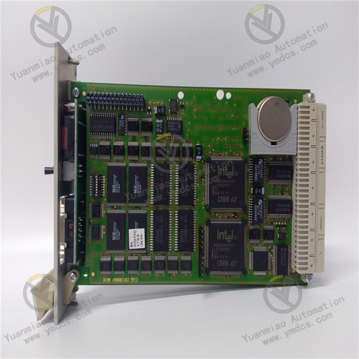
IS200JPDFG2AED is a dedicated high-speed pulse acquisition and frequency monitoring board for the GE Mark VI / Mark VIe turbine control system, serving as a core I/O module of gas and steam turbine main control systems. Designed for high-precision rotational speed monitoring, gear tooth frequency acquisition and pulse signal discrimination of rotating machinery, this board adapts to harsh operating conditions of high-speed rotating equipment including gas turbines, steam turbines, large industrial fans and compressors. It acts as a critical hardware unit for unit speed control, overspeed protection, vibration interlock and operating condition tracing. Adopting an industrial ruggedized PCB architecture, it delivers outstanding vibration resistance, high temperature tolerance and electromagnetic interference immunity. Widely deployed in control systems for thermal power plants, combined cycle power stations and industrial drive turbines, it is commonly used for technical retrofits of legacy systems, in-situ replacement of faulty boards and system capacity expansion, featuring excellent compatibility.
Core Functions
The board undertakes five core tasks: high-speed pulse signal acquisition, frequency calculation, rotational speed conversion, fault discrimination and data uploading. It collects high-frequency pulse signals output by speed measuring probes, magnetoresistive sensors and Hall sensors on steam and gas turbines. Based on high-precision hardware counting algorithms, it calculates key parameters in real time including unit rotational speed, tooth frequency pulses and rotation cycle, providing accurate raw data for startup/shutdown speed control, steady-state closed-loop speed regulation, overspeed protection interlock and acceleration condition judgment. It also supports pulse anomaly monitoring, signal loss identification, waveform distortion detection and over-limit alarming. It instantly captures risks such as speed fluctuation, pulse interference, sensor failure and circuit abnormality, uploads fault information in a timely manner and coordinates with the main control system to execute protection interlock, alarm notification and unit interlock actions. It prevents severe safety incidents such as overspeed runaway, speed instability and equipment resonance, ensuring safe and controllable operation of large rotating units throughout the operating cycle.
Compatible Systems
Fully compatible with the complete GE Mark VI and Mark VIe turbine control systems, matching the main control architecture of thermal power combined cycle units, gas-steam combined cycle power plants and industrial turbine units. It seamlessly cooperates with main CPU cards, analog I/O cards, digital I/O cards and communication boards, conforming to original system logic, backplane bus protocols and cabinet installation specifications. It supports compatible replacement between new and legacy systems and can directly substitute older boards of the same series without modifying control programs or logic. Suitable for supporting new unit construction, control system retrofits in aged power plants, spare parts replacement and system performance upgrading.
Application Scenarios
It is mainly applied to rotational speed monitoring and pulse signal acquisition of high-speed rotating power equipment such as large gas turbines, steam turbines, industrial compressors and heavy-duty fans, widely used in thermal power plants, cogeneration stations, oil & gas chemical power workshops and large industrial drive systems. It supports unit overspeed protection (OPC), closed-loop speed control, acceleration rate judgment, gear fault monitoring and operating condition analysis of rotating machinery. Capable of enduring harsh industrial environments including high cabinet temperature, vibration, dust and strong electromagnetic interference, it meets stringent requirements of high reliability, high precision and uninterrupted operation for power station equipment.
2. Technical Features
High-Speed & High-Precision Pulse Acquisition for Accurate Speed Monitoring
Equipped with a dedicated high-speed pulse counting chip to support real-time acquisition and hardware-accelerated computation of high-frequency pulses with ultra-high sampling resolution, enabling accurate capture of weak pulse signals and subtle speed fluctuations. It rapidly completes real-time speed conversion, tooth frequency statistics and rotational acceleration calculation with extremely low measurement error. It fully satisfies technical requirements for precise speed regulation, overspeed protection and accurate condition judgment of large turbines, and effectively avoids control inaccuracy and false protection caused by sampling errors.
Wide-Temperature Vibration-Resistant Industrial Design for Superior Environmental Adaptability
Built with power-plant-grade ruggedized hardware and wide-temperature industrial components. The PCB undergoes anti-vibration, moisture-proof and anti-corrosion treatment to withstand unit vibration, high cabinet temperature and humidity variation. No parameter drift, counting disorder or signal distortion occurs during long-term continuous operation. Its stability exceeds ordinary industrial acquisition boards and meets the demand of 24/7 unattended operation in power stations.
Multi-Stage Signal Filtering & Discrimination with Excellent Anti-Interference Performance
Integrated multi-level hardware filtering, software debounce and pulse discrimination algorithms automatically reject invalid signals including on-site electromagnetic interference, line noise, transient spurious pulses and waveform distortion, and identify valid speed measurement pulses reliably. It effectively mitigates pulse jitter, miscounting and signal hopping under strong electromagnetic conditions in power plants, ensuring authentic and stable speed data to underpin precise unit control and reliable protection.
Real-Time On-Board Diagnostics for Proactive Risk Identificatio
Comprehensive self-diagnosis and signal loop monitoring continuously track board hardware status, pulse input channel conditions, signal integrity and counting logic operation. It actively identifies sensor open circuit, line short circuit, signal loss, abnormal pulses and hardware faults. Alarms and fault codes are generated instantly to help maintenance personnel quickly locate defects and eliminate hidden dangers before signal anomalies trigger unit control failures and safety risks.
Native Original Bus Protocol Support for High System Compatibility
Natively compatible with the backplane bus communication protocol of GE Mark VI / Mark VIe systems. Plug-and-play without extra protocol configuration. Millisecond-level data exchange with the main controller enables real-time uploading of rotational speed, pulse frequency, operating status and fault information. It fully complies with original control logic, interlock protection rules and data interaction standards without compatibility conflicts, and fits system upgrading and replacement for both new and legacy units.
Standardized Modular Design for Convenient Maintenance & Replacement
Adopting standardized modular structure for GE control systems with uniform dimensions and interfaces, designed for rack-mounted hot-swappable installation featuring easy assembly and strong interchangeability. It supports full-range power-on self-test, online status monitoring and precise fault code reporting; troubleshooting can be completed without disassembly. Damaged legacy boards can be directly replaced in-situ without rewiring or program modification, greatly shortening unit downtime and reducing power plant maintenance costs and generation losses.
Multi-Layer Electrical Protection for Reliable Operation Safety
The board integrates protection circuits against overvoltage, overcurrent, electrostatic discharge, surge and electrical fast transient pulses. Comprehensive electrical and signal isolation effectively suppress electrical hazards in power plants such as high-voltage interference, voltage fluctuation, electrostatic surge and line transients. It prevents board breakdown, signal burnout and logic disorder to guarantee long-term stable and safe operation of the board and the whole control system.
3. Specification Parameters
| Item | Parameter |
|---|---|
| Model | IS200JPDFG2AED |
| Manufacturer | GE General Electric |
| Series | Mark VI / Mark VIe Turbine Control System |
| Equipment Type | High-Speed Pulse Frequency Counter Card, Unit Speed Monitoring I/O Module |
| Applicable Equipment | Gas Turbine, Steam Turbine, Industrial Compressor, Large High-Speed Rotating Machinery |
| Applicable System | GE Mark VI, Mark VIe Main Control System |
| Core Functions | High-Frequency Pulse Acquisition, Frequency Counting Calculation, Rotational Speed Conversion, Pulse Signal Discrimination, Loop Fault Monitoring, Data Uploading, Interlock Alarm |
| Supported Signal Types | Magnetoresistive Speed Pulse, Hall Pulse, High-Speed Square Wave Pulse |
| Acquisition Accuracy | Millisecond-level response, high-precision pulse counting, speed measurement error ≤0.1% |
| Operating Power Supply | Standard backplane power supply from the system |
| Communication Mode | High-speed system backplane bus communication |
| Core Application Logic | Closed-Loop Unit Speed Control, Overspeed Protection, Acceleration Rate Judgment, Gear Condition Monitoring, Pulse Fault Interlock |
| Protection Functions | Overvoltage & Overcurrent Protection, ESD Protection, Surge Suppression, Signal Filtering, Circuit Open-Circuit Monitoring, Abnormal Pulse Discrimination |
| Operating Temperature | -30℃~+75℃ |
| Storage Temperature | -40℃~+85℃ |
| Ambient Humidity | 5%~95%RH, non-condensing, suitable for power station cabinet environment |
| Electrical Characteristics | Electrical Isolation, Electromagnetic Shielding, Multi-Stage Signal Filtering, High Electromagnetic Immunity, Anti-Transient Interference |
| Mechanical Features | Standard Rack Hot-Swap Board, Modular Structure, Unified Original Interfaces, High Interchangeability |
| O&M Features | Full Power-On Self-Test, Precise Fault Code Reporting, Online Monitoring, In-Situ Replacement, No Program Commissioning Required |
| Product Characteristics | High Sampling Precision, Fast Response, Strong Anti-Interference, Vibration & Temperature Resistant, Complete Diagnostics, Wide Compatibility, Stable Performance, Easy Maintenance |
4. Working Principle
4.1 Power-On Initialization and Full-Range Hardware Self-Test
After receiving power from the system backplane, the board automatically executes hardware initialization, driver loading, bus protocol matching, channel verification and comprehensive self-diagnosis. It sequentially inspects pulse acquisition channels, counting chips, bus communication ports, power supply circuits, filter circuits and signal processing units to detect hardware damage, channel failure, circuit faults and communication breakdown. Once self-test passes, parameters and acquisition logic are synchronized with the main control system. The board enters real-time monitoring mode and stands by for pulse acquisition, speed calculation and data uploading.
4.2 High-Speed Pulse Acquisition and Filter Processing
During unit operation, the board continuously receives raw high-frequency pulse signals from speed sensors. Via built-in multi-stage hardware filters and software discrimination algorithms, electromagnetic interference, line noise, transient jitter and distorted invalid pulses are filtered out, retaining valid speed measurement pulses. Raw signals undergo waveform shaping, noise reduction and validation to eliminate miscounting and missing counting caused by interference, ensuring authentic and stable input signals as reliable data sources for subsequent speed computation.
4.3 Pulse Frequency Calculation and Rotational Speed Conversion
The core counting chip performs high-speed hardware counting and frequency statistics on valid pulses. Combined with gear tooth number, sensor calibration parameters and predefined conversion formulas, it calculates instantaneous speed, average speed, speed change rate and pulse frequency in real time. Computation is low-latency without data lag. Subtle speed variations during startup, acceleration, steady-state operation and load fluctuation are captured accurately. High-precision speed data serves as the fundamental input for closed-loop speed regulation, condition judgment and protection triggering.
4.4 Real-Time Condition Monitoring and Abnormality Discrimination
The board continuously monitors pulse status and computational data stability and analyzes variation trends of rotational speed and pulse frequency. When signal loss, pulse interruption, over-limit speed, speed hopping or abnormal fluctuation is detected, fault type and location are identified automatically. Local alarms are triggered immediately, and fault codes together with abnormal data are uploaded to the main controller. Signal anomaly interlock commands are output to prevent erroneous speed regulation and false protection induced by abnormal data and maintain stable control logic.
4.5 Bus Data Exchange and System Coordinated Control
Through the original high-speed backplane bus, real-time rotational speed, pulse frequency, equipment status and fault information are transmitted to the main CPU within milliseconds. It cooperates with the main control system to implement core control logic including closed-loop speed regulation, acceleration control, overspeed interlock and threshold judgment. Meanwhile, it receives configuration and calibration commands from the main controller to adapt dynamically to diverse operating modes, realizing seamless coordination between the board and the whole control system for stable unit operation under all working conditions.
4.6 Continuous Diagnostics and Safety Protection Mechanism
Hardware and software dual self-diagnosis runs continuously throughout operation to monitor power supply, chip operation, channel status and communication link integrity. If board degradation, channel damage, circuit short/open circuit or communication failure is detected, fault information is reported actively and faulty acquisition channels are interlocked. Erroneous data is blocked from entering the main controller to avoid control disorder, false protection and equipment runaway risks, comprehensively safeguarding unit safety.
5. Common Faults and Troubleshooting
5.1 Symptom: No Data Uploaded, Unit Speed Display Lost, Pulse Acquisition Failure
Possible Causes
① Abnormal backplane power supply, poor contact, oxidized and loose cabinet slot;
② Damaged speed sensor, broken/shorted signal cable or loose wiring;
③ Damaged acquisition channel, faulty counting chip or hardware failure on the board;
④ Abnormal bus communication, protocol mismatch and data transmission interruption;
⑤ Abnormal firmware, failed initialization or lost parameters.
Solutions
Shut down the unit and cut off power. Extract the board, clean gold fingers and cabinet slots to remove oxidation and dust, then reinsert firmly. Measure backplane supply voltage and troubleshoot power circuit defects. Inspect speed sensors and signal cables segment by segment, repair open/short circuits and replace defective sensors. Verify bus communication status and re-synchronize parameters between the board and main controller. Reboot the system to complete initialization calibration. If acquisition remains unavailable after all rectification, hardware damage is confirmed. Replace with original IS200JPDFG2AED board.
5.2 Symptom: Fluctuating Speed Readings, Inaccurate Values and Frequent Transient Alarms
Possible Causes
① Severe on-site electromagnetic interference without proper shielding and grounding for signal cables;
② Misaligned speed probe with excessive gap leading to unstable pulse collection;
③ Degraded filter modules with weakened anti-interference capability unable to suppress noise;
④ Aging signal cables with reduced insulation resulting in signal crosstalk and distortion;
⑤ Drifted sampling precision and abnormal counting logic on the board.
Solutions
Optimize shielding and grounding of speed signal cables; route away from high-voltage cables and frequency converters. Recalibrate installation position and gap of speed sensors and secure probes against vibration displacement. Fully test insulation performance of signal cables and replace aged wiring. Inspect filter circuit operation and remove accumulated dust on the board to improve thermal conditions. Calibrate and reset sampling precision. If speed hopping and frequent alarms persist after rectification, board performance degradation is confirmed and spare part replacement is required.
5.3 Symptom: False Unit Overspeed Protection and Accidental Speed Interlock Activation
Possible Causes
① Failed abnormal pulse discrimination; interference noise misrecognized as valid speed pulses;
② Transient speed reading jump triggering protection thresholds;
③ Disordered counting logic or abnormal firmware operation;
④ Transient short circuit or grounding anomaly in signal loop causing data mutation;
⑤ Improperly tuned system protection parameters and insufficient anti-chatter delay.
Solutions
Verify speed protection thresholds and anti-chatter delay parameters; optimize settings according to unit operating conditions. Thoroughly eliminate grounding, short-circuit and crosstalk risks in signal loops to avoid transient signal anomalies. Clean the board and reboot the system to refresh underlying logic. Test the effectiveness of pulse discrimination and filtering functions. If false protection still occurs after eliminating wiring, parameter and system issues, hardware fault exists and original board replacement is needed.
5.4 Symptom: Board Communication Interruption, System Fails to Recognize the Board, Offline Status
Possible Causes
① Oxidized gold fingers, poor slot contact leading to bus communication anomaly;
② Aging communication chip or damaged port resulting in failed bus interaction;
③ Faulty system backplane bus or abnormal channel occupation;
④ Corrupted board firmware unable to match system protocols;
⑤ Vibration in cabinet causing loose board and poor contact.
Solutions
Power off, remove the board, clean gold fingers and slots with dedicated cleaner and lock firmly after reinstallation. Inspect backplane bus operation and troubleshoot bus and channel abnormalities. Re-flash compatible firmware and restore factory configuration. Strengthen cabinet vibration damping to prevent board loosening. If the system still cannot identify the board and communication remains interrupted after all rectification, the communication module is damaged and replacement is required.
5.5 Symptom: Board Over-Temperature Alarm, Unstable Operation and Persistent Abnormal Status
Possible Causes
① Excessive dust inside control cabinet, blocked air duct and poor ventilation leading to high cabinet temperature;
② Long-term heavy-load computation accelerating component aging and heat generation;
③ Ambient temperature/humidity exceeding rated operating range;
④ Aging internal circuits with abnormal power consumption and degraded thermal stability.
Solutions
Periodically shut down equipment to clean cabinet air ducts, filters and dust on board surfaces, unblock cooling channels and improve ventilation. Control ambient cabinet temperature to keep operation within specified range. Regularly monitor board temperature and operating status to detect abnormal heat generation early. Replace aged IS200JPDFG2AED boards with recurrent over-temperature alarms and unstable operation in a timely manner to guarantee reliable speed monitoring and protection systems of the unit.