Description
1. Product Overview
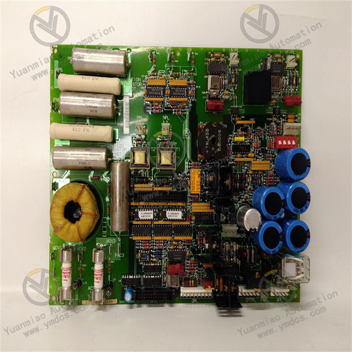
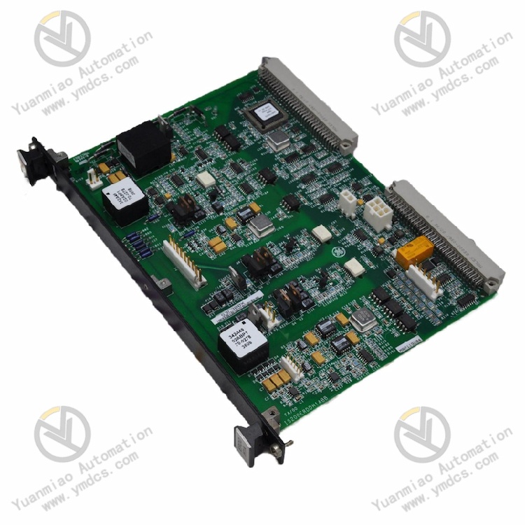
Part Number: IS200ERDDH1A, common revised version IS200ERDDH1ABB
Manufacturer: General Electric (GE). It is a core power drive and dynamic discharge board for the EX2100/EX2100e generator excitation regulation system and Speedtronic Mark VI/VIe gas & steam turbine main control platform. Only factory surplus stock, refurbished used and project redundant spare parts are available, serving as a critical key spare part for excitation cabinets of combined-cycle thermal power units, large hydropower units and captive power plants in chemical industry.
Backplane Compatibility & Architecture Modes
- Simplex Mode: A single module is installed on the ERBP Excitation Regulator Backplane, with master control over the K3 charging relay.
Redundant Mode: Two identical boards are required; one is mounted on the ERBP backplane, the other on the ERRB redundant relay backplane, to jointly control the K41 de-excitation crowbar relay. It supports TMR triple modular redundant voting logic and can be networked with ERIO I/O board, ERSC static rectifier power board and EROC option board for coordinated operation.
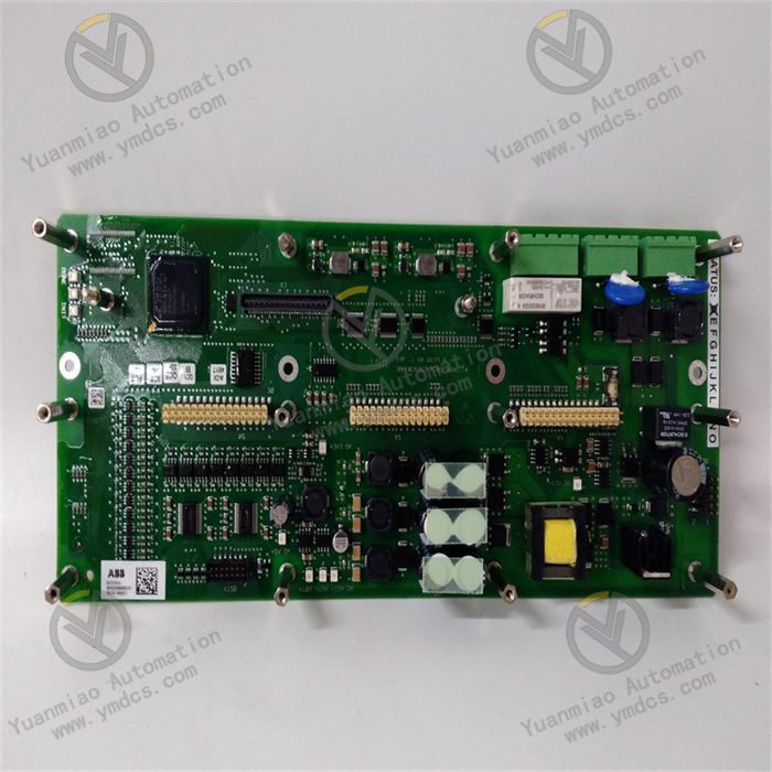
Product Definition: ERDD Excitation Dynamic Discharge Gate Drive Board, acting as the intermediate hub between the logic control layer and power rectifier layer of the excitation system. It receives low-level excitation regulation commands from the ERIO module, amplifies them into gate drive signals for IGBT/thyristor bridge circuits to drive the ERSC static excitation power unit for closed-loop regulation of generator excitation voltage. It continuously monitors DC link voltage, bridge output current and excitation winding voltage. In case of overvoltage caused by load rejection or regulator fault, the hardware-level trigger discharge branch is activated to drive de-excitation and charging relays to release excess energy, clamping voltage to a safe range. It features hardware safety interlock independent of the main CPU, serving as the bottom-layer protection core to prevent overvoltage, loss of excitation and device breakdown of the excitation system.
2. Six Core Hardware Functional Units
2.1 Backplane Bus Command Reception & FPGA Logic Calculation Unit
2.2 Multi-Channel Isolated Gate Drive Power Amplification Unit
2.3 DC Link Voltage Monitoring & Dynamic Discharge Protection Unit
2.4 Multi-Dimension Bridge Status Feedback Acquisition Unit
2.5 Relay Contact Output & Interlock Control Unit
2.6 Industrial Reinforced Conformal Coating & Environmental Adaptation Unit
3. Technical Specification
3.1 Basic Hardware Specifications
| Item | Specification |
|---|---|
| Base Part Number | IS200ERDDH1A (ABB suffix indicates hardware revision) |
| Rack Form Factor | Standard double-height single-slot VME card for Mark VI |
| Compatible System | Full EX2100/EX2100e Generator Excitation Control System |
| Core Interfaces | P1/P2 standard VME backplane edge connector + external feedback sampling terminals |
| Typical Power Consumption | ≤7W |
| Net Weight | Approx. 0.7kg |
| Origin | Original USA GE Manufacture |
3.2 Core Electrical & Control Parameters
- Drive Output: Multi-channel isolated IGBT gate trigger signals with timing error <1μs and isolation withstand voltage ≥2500VAC
- Bus Monitoring: Hardware threshold of DC link voltage can be solidified and set, overvoltage response time <5ms
- Relay Control: K3 charging relay in simplex mode; K41 de-excitation crowbar relay in redundant architecture
- Feedback Acquisition: Four-channel signal collection and upload including excitation output voltage, shunt current, power module temperature and drive fault
- Redundancy Rule: Simplex = 1 single card; TMR triple redundancy requires 3 sets of ERDD boards matched with complete redundant backplane for voting
- Fault Reporting: Detection and alarm upload for bus disconnection, drive open circuit, bus over/undervoltage and loss of feedback signal
3.3 Environmental & Safety Compliance
- Operating Temperature: -30℃ ~ +65℃
- Storage & Transport Temperature: -40℃ ~ +85℃
- Humidity: 5%~95%RH non-condensing, free of corrosive gas and salt fog deposition
- Ingress Protection: IP20, for installation only inside sealed industrial control cabinets
4. Product Advantages
- Dual-layer overvoltage protection architecture (upper software regulation + bottom independent hardware discharge circuit). Even if main control program crashes or communication is lost, hardware protection remains effective to maximize prevention of generator rotor insulation breakdown, serving as an irreplaceable safety barrier for the excitation system.
- Integrated drive and protection design consolidates pulse amplification drive, bus monitoring, fault sampling and relay interlock output on one single board, reducing cabinet hardware quantity and wiring points as well as intermediate link fault points. It is natively compatible with the EX2100 system with no third-party drop-in alternatives.
- Native compatibility with both simplex and redundant modes, flexibly adapting to simplex excitation for small units and triple modular redundant excitation design for critical large units. Multi-board voting eliminates false trip and protection refusal risks caused by single-point hardware faults.
- Full electrical isolation between control side and power drive side prevents reverse feed from power loop from burning out rack main control backplane and CPU core modules, confining faults to a single drive board and power bridge.
- Comprehensive built-in fault diagnosis accurately identifies damaged drive channels, abnormal bus voltage, broken sampling wires and relay loop anomalies with pop-up fault codes on upper monitoring HMI to shorten on-site troubleshooting cycles for power plant maintenance.
- Excellent backward compatibility with a large number of GE gas/steam turbine and hydropower unit EX2100 excitation systems in service domestically. Drop-in replacement reuses original configuration and field wiring with no control program modification required to minimize outage duration during emergency repair.
5. Application Scenarios
1. Combined-Cycle Thermal Power Gas & Steam Turbine EX2100 Excitation System
2. Large & Medium Hydropower Unit Excitation Control Cabinet
3. Captive Power Plants in Metallurgy & Chemical Industry Waste Heat Power Generation Systems
4. Retrofit & Spare Replacement for Legacy EX2100 Excitation Systems