Description
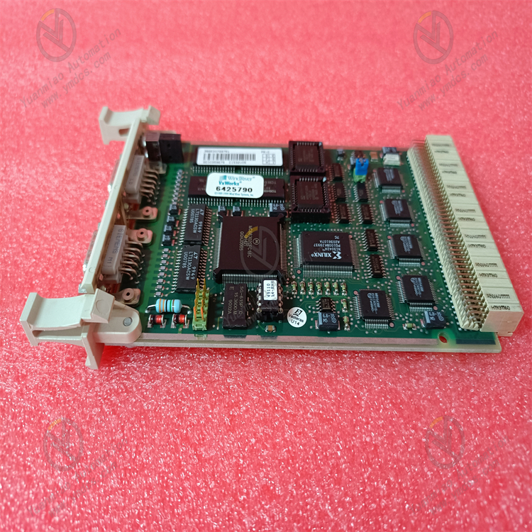
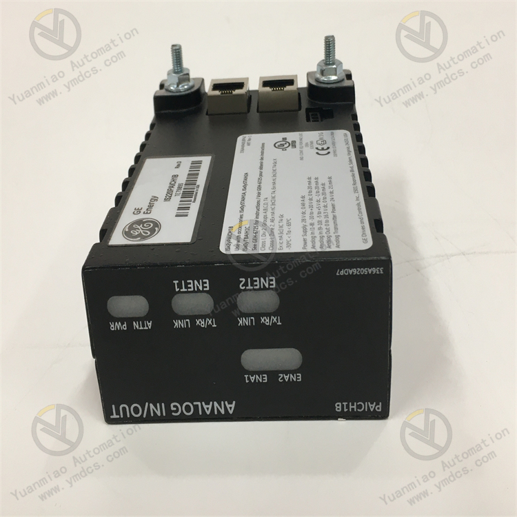
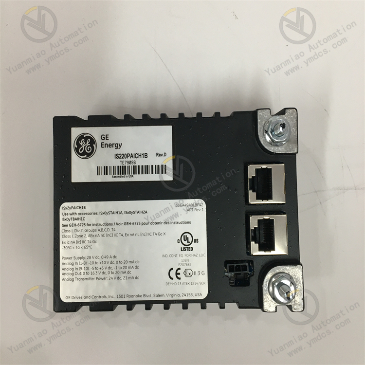
GE IS220PAICH1B
I. Functional Features
1. Core Functions
- Analog Input/Output Control
Supports processing analog signals (e.g., voltage, current, temperature, pressure) to achieve real-time monitoring and adjustment of industrial equipment. - Digital Input/Output Control
Capable of receiving and transmitting digital signals (switching quantities) for logic control, status monitoring, or equipment start/stop operations. - Communication Interfaces
Supports multiple industrial communication protocols (e.g., Ethernet, Modbus, PROFINET) to enable data interaction with host computers, PLCs, or other intelligent devices. - Redundancy Design
May feature hardware redundancy functions (e.g., dual power supplies, dual-module backup) to enhance system reliability and reduce downtime risks.
2. Technical Characteristics
- High Reliability
Uses industrial-grade components, adapts to harsh environments such as high temperature, vibration, and electromagnetic interference, and complies with industrial standards (e.g., IEEE, ISO). - High Precision and Real-Time Performance
Features fast data sampling and processing capabilities to ensure real-time response to equipment status and meet the high-precision requirements of control systems. - Flexible Configuration
Supports parameter configuration, logic programming, and function customization through software tools (e.g., GE's Proficy platform) to adapt to different application scenarios. - Diagnostics and Maintenance
Built-in self-diagnostic functions to monitor module status in real time (e.g., fault alarms, communication anomalies), facilitating quick problem Positioning (location) and resolution.
II. Application Scenarios
- Energy Industry: Control systems for gas turbines and steam turbines to achieve automated control of power generation equipment.
- Industrial Automation: Condition monitoring and closed-loop control of large mechanical equipment, such as compressors and pump units.
- Process Control: Continuous production process control in chemical, metallurgical, and other industries to ensure stable process parameters.
Technical Parameters
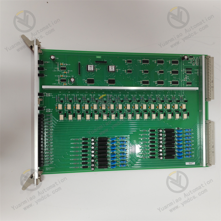
- I/O Channels: 12 channels per terminal block, including 10 analog inputs (AI) and 2 analog outputs (AO).
- Input Ranges:
- Inputs 1-8: 1-5V DC, ±5V DC, ±10V DC, or 0-20mA.
- Inputs 9-10: 0-20mA or ±1mA.
- Input Converter Resolution: 16-bit analog-to-digital converter.
- Scan Time: Normal scan at 5 ms (200Hz), maximum controller frame rate at 100Hz.
- Power Consumption: Typical 5.3W, worst case 6.2W.
- Power Supply:
- Voltage: 24VDC or 28VDC.
- Analog Transmitter Power: 22.8VDC.
- Operating Environment:
- Temperature Range: -40°C to 85°C.
- Humidity Range: 5% to 95% (non-condensing).
- Dimensions: Approximately 8.2×12.2×6 cm.
- Weight: Approximately 0.36 kg.
- Outputs:
- Output Ranges: 0-5V, 1-5V, 0-10V, -5-5V, -10-10V.
- Accuracy: ±0.1%.
- Resolution: 16-bit.
- Output Types: Analog outputs as 0-20mA current loop outputs; the PAICH2 version supports 0-200mA current on the first output, operating at 18V compatible voltage in simplex or TMR mode. Each analog output circuit also includes a normally open mechanical relay to enable or disable output operations.
Working Principle
GE's industrial automation modules (e.g., IS220 series) are typically used for data acquisition, signal processing, and system control, commonly found in control systems for power, chemical, manufacturing, and other industries. Their core working principles can be summarized in the following steps:
1. Signal Input and Acquisition
- Function: Receives various signals (e.g., analog, digital) from field devices (e.g., sensors, switches, instruments).
- Common Signal Types:
- Analog: Voltage (e.g., 0-10V), current (e.g., 4-20mA), temperature (e.g., thermocouple, RTD signals).
- Digital: Switch states (ON/OFF), pulse signals, etc.
- Principle: Preprocesses input signals through internal signal conditioning circuits (e.g., filtering, amplification, isolation) to ensure signal stability and anti-interference capability.
2. Analog-to-Digital Conversion (A/D Conversion, for analog signals)
- Function: Converts analog signals to digital signals for processing by controllers (e.g., PLC CPUs).
- Principle:
- Uses an analog-to-digital converter (ADC) to convert continuous analog quantities into discrete digital quantities (e.g., 12-bit or 16-bit binary numbers).
- Transmits converted digital signals to the controller via internal buses (e.g., Ethernet, PROFINET, Modbus).
3. Signal Processing and Logic Control
- Function: Performs logic processing, calculations, or comparison with preset thresholds on acquired signals to execute control commands.
- Principle:
- May have built-in microprocessors or logic circuits for simple local processing (e.g., signal alarms, linearization correction).
- Complex control logic is typically handled by upper-level controllers (e.g., GE's PAC system), with modules receiving commands and feeding back status via communication interfaces.
4. Signal Output and Execution (for output modules)
- Function: Converts the controller's digital signals to analog or digital quantities to drive field actuators (e.g., valves, motors, indicator lights).
- Principle:
- Digital-to-Analog Conversion (D/A): Uses a digital-to-analog converter (DAC) to convert digital signals to analog signals (e.g., 0-10V voltage, 4-20mA current).
- Digital Output: Emits ON/OFF signals via switching components (e.g., relays, transistors) to control equipment start/stop.
5. Communication and System Integration
- Function: Exchanges data with controllers, human-machine interfaces (HMIs), or other modules to achieve system-level coordinated control.
- Principle:
- Connects to upper-level systems via communication protocols (e.g., GE's CIP, EtherNet/IP, Profibus).
- Supports real-time data transmission, parameter configuration, fault diagnosis, and other functions.
6. Power Supply and Electrical Isolation
- Function: Ensures stable module power supply and isolates external interference.
- Principle:
- Powered by independent power supplies (e.g., 24V DC), with some modules supporting redundant power supplies.
- Uses optoelectronic isolation and electromagnetic isolation technologies to prevent field noise from affecting the control system.
Common Faults and Solutions for GE IS220PAICH1B Module
I. Common Fault Types and General Troubleshooting Directions
- Power Supply Faults
- Symptoms: Module indicator lights off, power light flickering or extinguishing abnormally; system error "Power Failure" or "Module Not Powered."
- Possible Causes: Abnormal power input (unstable voltage, reverse polarity, blown fuse); internal power circuit damage (aging capacitors, faulty chips); loose or damaged power cables.
Solutions:
- Check if input voltage matches the module's rated value (e.g., DC 24V or AC 220V) using a multimeter.
- Replace fuses with the same specification and check for external short circuits or overloads.
- Reconnect power connectors, tighten terminal blocks, and replace power cables if necessary.
- Contact the manufacturer for repair or replacement if internal power supply is damaged.
- Communication Faults
- Symptoms: Communication loss with the main control system (e.g., PLC controller), error "Communication Lost"; abnormal data transmission (e.g., input/output value jumps, no updates); communication indicator lights (e.g., RX/TX) not flashing or staying on/off.
- Possible Causes: Incorrect communication address settings (e.g., duplicate station numbers, mismatched baud rates); damaged or poorly connected communication cables (e.g., twisted pair, fiber optic), or missing termination resistors; faulty communication interface chips or abnormal firmware; electromagnetic interference causing signal distortion (e.g., near motors, frequency converters).
- Solutions:
- Verify that module communication parameters (address, baud rate, parity) match system settings; reconfigure and restart the module.
- Check communication cable connections, test for continuity, replace damaged cables, and ensure proper termination resistor installation (e.g., RS485 networks).
- Reset module firmware via system software or upgrade to the latest version (refer to official manuals).
- Add shielding to communication cables or relocate them away from interference sources; use signal isolators if necessary.
- Input/Output (I/O) Faults
- Symptoms: No response to input signals (e.g., no input indication when a button is pressed); output channels unable to drive loads (e.g., relays not actuating, indicator lights off); abnormal I/O channel values (e.g., analog input value fluctuations, out-of-range readings).
- Possible Causes: Faulty input signal sources (e.g., damaged sensors, no power supply); output channel overloads, short circuits, or load-side faults (e.g., motor jams); internal I/O circuit damage (e.g., burnt relay contacts, faulty analog conversion chips); incorrect wiring (e.g., mismatched input/output types, such as DC signals connected to AC channels).
- Solutions:
- Test signal sources (e.g., sensor power, output signals) and replace faulty sensors or transmitters.
- Inspect output load circuits for short circuits or overloads; replace damaged fuses or protective components.
- Use a multimeter to measure input/output signals at module terminals; repair or replace the module if internal circuits are damaged.
- Confirm wiring against the module manual and correct polarity or type errors (e.g., dry/wet contact differentiation).
- Overheating or Environmental Faults
- Symptoms: Excessive module temperature, hot surface, accompanied by abnormal fan operation or blocked cooling vents; internal short circuits or corrosion due to environmental humidity or dust.
- Possible Causes: Poor ventilation in the installation environment, faulty cooling fans, or dust accumulation; ambient temperature exceeding the module's rated range (e.g., >60°C); condensation or corrosive gases entering the module.
- Solutions:
- Clean cooling vents and fans, ensure good ventilation, and add external cooling devices if necessary.
- Check if ambient temperature is within the module's specified range (typically 0–55°C); reposition or add air conditioning/fans.
- Inspect module sealing, repair protective casings, control humidity with dehumidifiers, and apply anti-corrosion treatments if needed.
- Hardware Damage or Compatibility Issues
- Symptoms: Frequent error messages, system freezes, or failure to initialize; incompatibility with other hardware (e.g., expansion modules, interface cards) leading to system instability.
- Possible Causes: Component aging from long-term operation (e.g., bulging capacitors, cracked solder joints); motherboard or chipset failures (e.g., damaged FPGA, ASIC chips); hardware-software version incompatibility (e.g., old modules with new firmware).
- Solutions:
- Visually inspect internal components (e.g., leaking capacitors, burnt resistors); replace damaged components or the entire module.
- Ensure hardware and software versions are compatible per official compatibility lists; upgrade or downgrade firmware/software.
- Update motherboard drivers or contact the manufacturer for technical support in case of compatibility issues.