Description
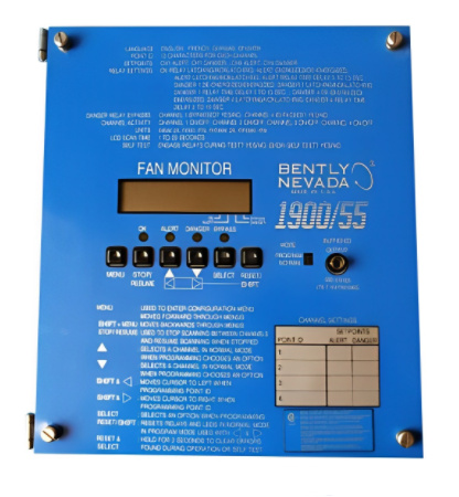
Bently Nevada 1900/55-01-01-01-00
I. Basic Information
Model: 1900/55-01-01-01-00Brand: Bently NevadaSupported Platform: 1900 Series Standalone Rotating Machinery Protection Monitoring System. It can operate independently without a 3500 rack and is specially designed for auxiliary equipment such as fans, water pumps and small compressors.Product Type: 4-channel standalone fan vibration monitoring controller compatible with Velomitor velocity vibration sensors. It can collect equipment vibration severity and rotational speed signals in real time, equipped with local LCD display, keypad configuration, relay alarm output and 4-20mA analog transmission output. It can independently realize over-limit alarm and interlock shutdown protection, serving as the core instrument spare part for condition monitoring and mechanical protection of auxiliary equipment in power plants, chemical and metallurgical industries.
Model Code Interpretation
1900/55: 4-channel vibration monitoring controller dedicated to fans in the 1900 Series, compatible with velocity sensors for low-frequency vibration measurement (1.5Hz~1000Hz)1st digit 01: Standard 24VDC power supply version2nd digit 01: Configuration with 4-channel relay alarm contact outputs3rd digit 01: 4 independent 4-20mA analog transmission outputs4th digit 00: Standard industrial cabinet mounting type without special explosion-proof certification
Product Positioning
1900/55-01-01-01-00 is a compact standalone monitoring instrument launched by Bently Nevada for small and medium-sized rotating auxiliary equipment. It requires no supporting rack and can be wall-mounted directly in on-site control cabinets. It supports connection of 4 Velomitor magnetoelectric velocity sensors to continuously monitor vibration of fan bearings and gearboxes. Equipped with front-panel keypad configuration and real-time LCD data display, it allows flexible setting of two-level alarm thresholds (warning and danger). Relay contacts act upon faults to implement local interlock protection, while vibration signals are converted into standard 4-20mA signals and uploaded to the DCS control system.The device adopts an industrial dust-proof reinforced design with strong electromagnetic interference resistance and stable performance over a wide temperature range, adapting to harsh on-site conditions of high temperature, dust and oil contamination. It enables early prediction of bearing wear, impeller unbalance and gear faults, prevents major equipment safety accidents such as fan runaway and blade fracture, and greatly reduces the risk of unplanned shutdowns of auxiliary machinery.
Hardware Architecture
The controller features an integrated dust-proof metal housing with a human-machine interaction front panel, isolated strong and weak current layout inside, and PCB coated with three-proof protective coating. Its hardware consists of six core units:
4-Channel Sensor Signal Acquisition & Conditioning Unit
It simultaneously receives AC signals from 4 magnetoelectric velocity sensors. Built-in programmable band-pass filter circuits accurately extract low-frequency vibration signals ranging from 1.5Hz to 1000Hz, adapting to low-speed fan operating conditions (minimum 90RPM). It suppresses industrial frequency and high-frequency electromagnetic interference from motors, converting raw vibration signals into standardized measured data.
High-Speed Data Calculation & Configuration Processing Unit
Equipped with an industrial-grade signal processing chip, it performs real-time conversion of vibration severity RMS values and calculation of rotational speed pulses. All parameter configurations including channel range, alarm thresholds, filter parameters and transmission range can be set via front-panel keys without upper computer software. A built-in power-fail parameter storage circuit ensures configuration data is permanently retained after power failure.
LCD Display & Human-Machine Interaction Unit
The backlit front-panel LCD screen cycles through real-time vibration values of 4 channels, current alarm status and fault codes. Function keys support parameter modification, alarm reset, channel testing and range calibration, as well as local one-click zero clearing and factory parameter restoration.
Relay Interlock Output Unit
Four independent passive relay contacts are integrated, with each channel configurable for two-level alarm actions (warning & danger). Contacts close instantly once the measured value exceeds the threshold, directly connecting to the equipment safety interlock loop to trigger audible and visual fan alarms as well as emergency shutdown protection. The contacts adopt anti-chatter delay design to avoid false interlocks caused by transient interference.
4-20mA Isolated Analog Transmission Unit
Four electrically isolated standard analog outputs convert each vibration measurement into a 4~20mA DC signal linearly corresponding to the configured range. The isolation design prevents interference from the DCS side from intruding into the controller, enabling remote centralized monitoring, trend storage and analysis of vibration data.
Industrial-Grade Power Supply & Protection Unit
The wide-range 24VDC power supply circuit integrates surge protection and reverse connection prevention circuits. The whole device complies with EMC electromagnetic compatibility standards, with PCB coated with three-proof paint and a grounded metal shielding housing to withstand on-site voltage fluctuations, static electricity and radio frequency interference.
Mounting Specifications
- Mounting Method: Standard flush cabinet panel mounting matching the cutout size of industrial control cabinets; also applicable for local wall-mounted cabinet installation
- Overall Dimensions: Front panel 249mm × 182mm, mounting depth 85mm
- Net Weight: Approx. 1.45kg
- Panel Interfaces: LCD screen, function setting keys, status indicators; Rear Terminals: sensor input terminals, 24VDC power terminals, 4×4-20mA analog output terminals, 4 relay alarm terminals
- Configuration Mode: Local keypad configuration without upper configuration software; supports parameter backup and factory reset
- Compatible Sensors: Bently Velomitor series magnetoelectric velocity sensors (Model 190501)
- Recommended Accessories: Double-shielded sensor signal cables, power filter terminals, relay lightning surge absorbers, grounding copper bars
Supporting System
Supporting Hardware
Velomitor vibration velocity sensors, 24VDC redundant switching power supply, double-shielded signal cables, audible and visual alarms, DCS analog acquisition cards, safety interlock relay loops.
Commissioning Tools
High-precision multimeter, signal generator, insulation resistance tester, torque wrench, sensor calibrator.
Upper-Level Connection System
Power / chemical plant DCS distributed control system, equipment condition monitoring platform, realizing real-time vibration data collection, trend curve storage, remote over-limit alarm and equipment fault traceability analysis.
Typical Application Industries
Induced draft fans, forced draft fans and primary air fans in thermal power plants; dust removal fans and circulating water pumps in metallurgical blast furnaces; compressors, cooling fans and large pump sets in chemical plants; aeration fans in sewage treatment plants and auxiliary equipment for waste heat power generation.
Product Features
- 4-Channel Independent Synchronous Monitoring for Multi-Point Bearing MeasurementA single controller monitors four vibration measuring points including fan drive end, non-drive end and gearbox. Each channel features independent range, alarm and transmission parameter settings with electrical isolation between channels. One unit can complete full vibration protection configuration for an entire fan unit.
- Full Local Keypad Configuration for Convenient On-Site Commissioning Without Upper SoftwareAll parameters including vibration range, high/low alarm thresholds, filter frequency, 4-20mA upper/lower limits, alarm delay and relay action mode can be customized via panel keys. Parameters are permanently saved after power failure, allowing quick parameter replication during on-site spare part replacement to greatly shorten commissioning downtime.
- Low-Frequency Optimized Signal Acquisition for Low-Speed Fan ApplicationsThe minimum measurable frequency reaches 1.5Hz, enabling accurate vibration monitoring for rotating equipment operating above 90RPM. It resolves issues of low-frequency signal distortion and measurement fluctuation in traditional monitoring instruments, perfectly meeting monitoring requirements for large induced draft fans and low-speed pump units.
- Dual Signal Output: Isolated Analog + Passive RelayFour independent isolated 4-20mA outputs transmit data to DCS, while four passive relay contacts implement local safety interlock. Electrical isolation between analog and acquisition loops fulfills both remote monitoring and local equipment safety protection requirements, providing dual safeguards for unit operation.
- Wide-Temperature Reinforced Industrial Design for Stable Operation in Harsh SitesWith a wide operating temperature range, dust-proof and anti-interference design, reverse connection and surge protection for power supply, a metal shielding housing and PCB three-proof coating, the controller supports 24/7 uninterrupted operation in dusty, oily and high-electromagnetic-interference auxiliary equipment sites.
- Comprehensive Local Fault Diagnosis for Rapid Maintenance TroubleshootingBuilt-in self-diagnosis functions detect sensor open circuit, short circuit, over-range and power supply faults. Corresponding channel indicators light up and fault codes are locked upon failure, enabling quick troubleshooting of common on-site faults such as cable damage, sensor failure and abnormal power supply to reduce maintenance difficulty.
II. Technical Specifications
1. Electrical Parameters for Signal Acquisition
- Measuring Channels: 4 independent velocity vibration input channels
- Compatible Sensors: Velomitor magnetoelectric velocity sensors with AC voltage input
- Measuring Frequency Range: 1.5Hz ~ 1000Hz (±3dB)
- Standard Measuring Range: 0~50mm/s (user-configurable via front panel)
- Measuring Accuracy: ≤±1% FS
- Filter Mode: Programmable digital high-pass and low-pass filters to suppress power frequency interference
- Rotational Speed Measurement: Calculable via vibration pulse signals
2. Output Interface Parameters
- Analog Output: 4 isolated 4~20mA DC outputs with independent range mapping per channel, maximum load 500Ω
- Relay Output: 4 normally open passive relay contacts, contact rating 250VAC/5A, 30VDC/5A; supports alarm anti-chatter delay setting
- Alarm Mode: Two independent threshold levels (Warning / Danger) per channel; configurable for alarm latch or auto-reset
3. Power Supply Electrical Parameters
- Rated Operating Power Supply: 24VDC
- Allowable Voltage Fluctuation: 18VDC ~ 32VDC
- Total Rated Power Consumption: ≤15W
- Power Supply Protection: Hardware protection against reverse connection, overvoltage, surge and short circuit
4. Environmental Specifications
- Standard Operating Temperature: -10℃ ~ +55℃ (fully loaded operation in sealed cabinets)
- Storage & Transportation Temperature: -25℃ ~ +70℃
- Operating Relative Humidity: 5% ~ 95% RH, non-condensing, no corrosive gas
- Ingress Protection Rating: IP30 (front panel dust-proof; for installation only in sealed industrial control cabinets)
- MTBF (Mean Time Between Failures): ≥250000 hours
5. Mechanical & Physical Parameters
- Mounting Method: Flush panel mounting in control cabinets
- Front Panel Dimensions: 249mm (W) × 182mm (H), mounting depth 85mm
- Net Weight: 1.45kg
- Housing Material: Electrostatic sprayed dust-proof cold-rolled steel plate with internal isolated layout for strong and weak currents
- Protection Process: PCB coated with three-proof anti-corrosion paint; electrical isolation for power and analog loops
III. Key Features
- Continuous Independent Low-Frequency Vibration Monitoring over Four ChannelsCollect vibration severity at multiple bearing measuring points of fans and pumps synchronously, accurately capturing early bearing and gear fault characteristics of low-speed rotating equipment to provide reliable measurement data for predictive maintenance.
- Full Parameter Configuration & Status Display via Local Front PanelAll channel parameters and alarm thresholds can be set via panel keys without upper software. The LCD displays real-time 4-channel vibration values, alarms and fault status, supporting local manual alarm reset and parameter calibration.
- Two-Level Alarm + Relay Interlock ProtectionWarning and danger thresholds can be set for each channel. Relay passive contacts act upon fault triggering to connect audible & visual alarms and unit interlock loops, reminding maintenance personnel for inspection and triggering automatic shutdown under extreme faults to prevent severe equipment damage.
- Remote Data Upload via Four Isolated Standard 4-20mA SignalsEach measured signal is converted into industry-standard analog quantity with electrical isolation to avoid cross-system interference. Vibration data is uploaded to the DCS system for centralized plant-wide auxiliary equipment monitoring, trend analysis and fault tracing.
- Hardware-Level Fault Self-Check & Power-Fail Parameter StorageReal-time monitoring of sensor open/short circuit, abnormal power supply and signal over-range faults with locked fault codes for convenient on-site troubleshooting. All configuration parameters are stored in non-volatile memory and retained after power failure or restart.
- Standard Industrial Interface for Rapid On-Site Spare Part ReplacementUnified terminal definitions and panel mounting dimensions allow direct in-situ replacement of same-model controllers. Only parameter re-entry is required for commissioning without modification to cabinet wiring or interlock loops, significantly shortening equipment maintenance downtime.
IV. Working Principle
After power-on self-test and parameter initialization, the four acquisition channels continuously receive alternating velocity signals output by Velomitor magnetoelectric sensors. Internal conditioning circuits filter, amplify and convert raw signals into digital values. The arithmetic chip converts AC vibration signals into RMS vibration severity values and calibrates readings according to user-defined panel ranges.Real-time measurement data is displayed cyclically on the front LCD panel and compared with preset warning and danger thresholds for each channel. When readings exceed thresholds, corresponding channel indicators illuminate, internal relay contacts close to output interlock switch signals, and vibration values are linearly converted into isolated 4~20mA analog signals uploaded to the DCS control system.The device continuously diagnoses input signals, supply voltage and hardware loops during operation. Once sensor open/short circuit or power supply anomalies are detected, fault codes are locked and alarm prompts activated. All user-configured range, alarm and filter parameters are stored in non-volatile memory and permanently retained after power loss to restore original operating configurations upon restart, providing stable vibration monitoring and safety protection for rotating auxiliary equipment.
V. Application Scenarios
- Boiler Auxiliary Equipment Monitoring in Thermal Power Plants: Four-channel bearing vibration monitoring, over-limit alarm and interlock protection for induced draft fans, forced draft fans, primary air fans, pulverized coal exhaust fans and circulating water pumps.
- Petrochemical Process Equipment: Online vibration monitoring for cooling fans, air compressors, circulating pumps and Roots blowers to realize early equipment fault warning and prevent unplanned plant shutdowns.
- Large Fan Equipment in Metallurgical & Cement Industries: Bearing vibration protection for blast furnace dust removal fans, kiln exhaust fans and raw material conveying fans to ensure stable operation of continuous production lines.
- Auxiliary Equipment for Sewage Treatment & Waste Heat Power Generation: Condition monitoring for aeration fans, circulating water pumps and condensate pumps to realize unattended remote monitoring of auxiliary machinery.
- Technical Retrofit & Replacement of Legacy Field Instruments: Upgrade of traditional pointer vibration meters and simple alarm instruments via in-situ installation, reusing original sensors, interlock and DCS wiring loops to reduce retrofit construction and commissioning costs.