Description
1. Product Overview
ABB TB820V2, part number 3BSE013208R1, is a non-redundant fiber-optic ModuleBus cluster modem for the S800 I/O system. It is compatible with System 800xA and AC800M distributed DCS control systems, and serves as the core communication unit for signal conversion between electrical ModuleBus and fiber-optic ModuleBus.
Integrated with an electrical bus interface, dual fiber optic ports, isolated power supply circuit and real-time status monitoring circuit, this modem supports up to 12 S800 I/O modules on its local electrical bus, and can expand a maximum of 7 I/O clusters via fiber links with a maximum fiber transmission distance of 20 km. Fiber optics completely isolate electromagnetic interference caused by ground potential differences, frequency converters and high-voltage switchgears, solving unstable communication issues arising from excessive I/O modules in large I/O stations, scattered cabinet layout over long distances and high electromagnetic interference environments.
A built-in power isolation circuit supplies isolated power to local DIN rail-mounted I/O modules. The front panel is equipped with status indicator LEDs and a rotary DIP switch for cluster address setting, and the unit shall be used together with TB807 bus terminating resistors. Hot swapping is not supported. Featuring industrial wide-temperature hardware and IP20 indoor protection, the product has obtained multiple industrial certifications including CE, UL, ATEX C1 Div2 and ABS marine certification. It is widely applied in expansion projects of large DCS I/O cabinets, distributed remote I/O cluster networking, and communication interference rectification of legacy electrical bus systems in thermal power, chemical, metallurgical and water treatment industries.
2. Hardware Structure and Composition
2.1 Electrical/Fiber Optic Signal Conversion Processing Unit
A dedicated optoelectronic conversion chip enables bidirectional conversion between electrical ModuleBus signals and optical fiber signals, which logically belong to one unified bus link. The local electrical bus receives data from DIN rail I/O modules, converts the data into optical signals and transmits them to the upper-level controller or other clusters through dual fiber ports. Meanwhile, it converts downlink optical signals back into electrical signals and distributes them to local I/O cards. Real-time data packaging, decoding and timing scheduling are executed without occupying the controller’s CPU resources.
2.2 Dual Fiber Optic Port Communication Unit
Two fiber transceiving ports (Tx/Rx) are provided to support multi-mode / single-mode fiber cabling for long-distance bus cascading between clusters. Signal intensity detection circuits are built into the optical ports. Once fiber breakage or optical power attenuation occurs, front panel alarms will be triggered immediately, and fault codes will be uploaded to the DCS system to distinguish faults of fiber links and local I/O buses.
2.3 Local Electrical ModuleBus Bus Unit
A standard ModuleBus electrical interface is arranged at the bottom, which cascades TU series terminal units and all types of S800 I/O modules via the DIN rail backplane. A single modem’s electrical bus can carry a maximum of 12 I/O cards. Short-circuit and overcurrent protection are integrated into the bus loop; short-circuit of a single I/O terminal unit will only cut off the local branch without affecting communication of upper-level fiber clusters.
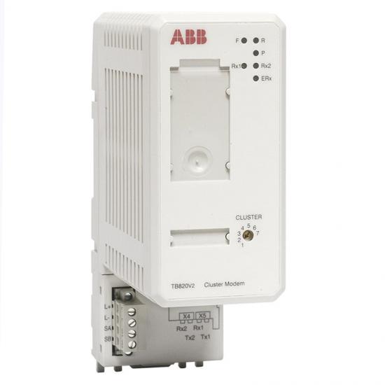
2.4 Cluster Address DIP Switch & Status Indication Unit
A rotary DIP switch with gears 1 to 7 is mounted on the front panel to set the local fiber cluster ID for distinguishing 7 separate remote I/O clusters. Four LED status indicators are fitted on the panel: PWR for power supply, BUS for local bus, Rx for fiber reception and Tx for fiber transmission, which visually display real-time operating status of power supply, local bus and fiber transceiving. The corresponding LED will stay on to alert operators upon faults.
2.5 Isolated Power Supply & Hardware Protection Unit
The unit accepts external 24VDC DC input. A built-in isolated power conversion circuit provides isolated working power for all DIN rail-mounted I/O modules and blocks clutter and ground potential interference from the external power grid. Four tiers of hardware protection (overvoltage, undervoltage, reverse polarity and short-circuit protection) are integrated. The bus output will be automatically cut off upon power supply abnormalities to prevent burnout of downstream I/O cards.
2.6 Standardized DIN Rail Housing Unit
Integrated housing made of V0 flame-retardant engineering plastic, with a single-slot modular size standard for S800 I/O products, designed for horizontal mounting on standard 35mm DIN rails. No moving mechanical parts are adopted. Gold-plated PCB contacts resist oxidation to guarantee stable long-term constant-temperature operation in sealed control cabinets. The unit contains no consumable parts and requires no routine mechanical maintenance.
3. Technical Specifications
(1) Communication Performance Specifications
Model & Part No.: TB820V2 / 3BSE013208R1
Bus Protocol: ModuleBus
Max. Number of I/O Modules Supported on Local Electrical Bus: 12
Max. Number of Clusters Supported via Fiber Links: 7
Max. Fiber Transmission Distance: 20 km (compatible with single-mode / multi-mode fiber)
Fiber Interfaces: Dual Tx/Rx optical ports
Address Configuration: Rotary DIP switch with gears 1–7 for cluster ID assignment
Signal Conversion: Bidirectional real-time conversion between electrical signals and optical signals
Bus Monitoring: Online diagnosis of local bus faults, fiber breakage and optical power attenuation
(2) Overall Electrical Specifications
Rated Supply Voltage: 24VDC (allowable range: 18~30VDC)
Typical Operating Current: 100mA @ 24VDC
Max. Overall Power Consumption: ≤2.4W
Power Isolation: Built-in isolated power supply for local I/O modules
Matching Terminal Accessory: TB807 ModuleBus bus terminating resistor
Hot Swap Support: Hot swapping of modules is not supported
Compatible I/O Series: Full range of S800 AI/AO/DI/DO and pulse counting I/O cards
(3) Environmental Protection Specifications
Operating Temperature (Horizontal Rail Mount): 0℃ ~ +55℃
Operating Temperature (Vertical Rail Mount): 0℃ ~ +40℃
Storage & Transportation Temperature: -40℃ ~ +70℃
Relative Humidity: 5%~95% RH, non-condensing, free of acid and alkali corrosive gas
Protection Class: IP20 (for indoor control cabinet installation only)
Pollution Degree: Class 2
(4) Mechanical Installation Specifications
Mounting Method: Horizontal clip-on mounting on standard 35mm DIN rail
Overall Dimensions: W58mm × H170mm × D122mm
Net Weight: Approx. 0.3kg
Housing Material: High-temperature resistant V0 flame-retardant engineering plastic, gold-plated PCB contacts
Support Configuration Software: ABB Control Builder / 800xA System Platform
4. Product Functions and Features
Bidirectional optoelectronic signal conversion breaks distance and interference limits of electrical buses
Fiber optics completely isolate electromagnetic interference, eliminating issues such as electrical bus disconnection and signal drift caused by high-power frequency converters, high-voltage switch rooms and strong magnetic fields in metallurgical plants. Fiber cabling up to 20 km enables long-distance networking of scattered multi-cabinet I/O clusters in workshops without signal attenuation limitations of copper cables.
Flexible cluster expansion breaks the upper limit of I/O modules per single DIN rail
A single electrical bus supports up to 12 I/O modules, and a maximum of 7 independent I/O clusters can be cascaded via fiber links. For large-scale plants, massive measuring points can be expanded by adding fiber modems without installing extra controllers, significantly reducing system hardware investment and configuration workload.
Isolated power supply improves anti-interference performance of the whole I/O station
The built-in independent isolated power supply circuit supplies isolated power to all AI/DI/AO/DO modules on the DIN rail, eliminating analog signal fluctuation and digital signal false triggering induced by ground potential differences between field instruments and actuators, and improving measurement and control accuracy.
Full-link real-time fault diagnosis enables rapid communication fault location
The unit continuously monitors faults including short-circuit of local electrical bus, offline I/O modules, fiber breakage, optical power attenuation and power supply under/overvoltage. Front panel LEDs provide visual alarms, and fault codes are uploaded to the DCS system to generate SOE events. Maintenance staff can quickly distinguish local I/O faults and remote fiber link faults to shorten downtime troubleshooting duration.
Standardized S800 architecture ensures compatibility for new and old system renovation
Unified mechanical dimensions, bus definitions and DIN rail mounting specifications allow existing single-cabinet I/O stations to be expanded with remote clusters by adding TB820V2 units. Original TU series terminal units and I/O cards can be retained without replacement, and expansion renovation can be completed merely by laying fiber cables with short plant shutdown time.
Multi-industry safety certifications suit special working conditions such as explosion-proof areas and ships
The product holds explosion-proof and marine certifications, applicable to I/O cabinets in chemical explosion-proof zones, offshore platforms and marine power control systems. The wide-temperature hardware adapts to harsh environments including low temperature in winter and high temperature inside cabinets in summer, supporting stable 24/7 continuous operation all year round.
![]()