Description
1. Product Overview
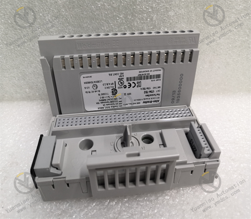
Allen‑Bradley 1794‑TB2 is a standard 2‑wire cage‑clamp terminal base of the FLEX I/O series manufactured by Rockwell Automation. It is a dedicated matching base for 1794‑series distributed I/O modules and serves as the core wiring and mounting carrier for small‑and‑medium‑sized automation control systems and remote I/O stations. Featuring a classic universal 2‑wire wiring structure, this terminal base is specially designed for conventional 2‑wire digital input and output modules. With compact structure, reliable wiring and outstanding universality, it is widely compatible with standard digital I/O modules across the entire 1794 product range.
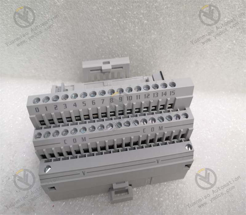
The 1794‑TB2 adopts industrial cage‑clamp screw termination and supports general‑purpose copper‑core cables. It integrates 16 I/O signal terminals, common terminals and power supply terminals to facilitate fast and orderly connection of signal cables and power cables for I/O modules. Constructed as a pure mechanical wiring base without complex circuitry, it delivers high anti‑interference performance, low failure rate and maintenance‑free operation, suitable for regular electromagnetic conditions and long‑term continuous‑run industrial environments. As the most widely‑used basic terminal base within the FLEX I/O system, it is extensively deployed for I/O system assembly, equipment maintenance and retrofitting of legacy automation systems in production lines, packaging machinery, water‑treatment, HVAC, light‑industry and chemical‑process automation. It represents the standard base with optimum cost‑performance and broad compatibility within Allen‑Bradley distributed I/O architectureRockwell A....
2. Functional Features
2.1 Standard 2‑Wire Wiring Architecture for Conventional Digital I/O Applications
Designed for industrial 2‑wire digital signals, it eliminates complex 3‑wire signal loops and is compatible with most discrete‑input, transistor‑output and relay‑output modules. Terminals for signals, common points and power supply are arranged in separate zones for clear loop logic. Optimized for standard DC24V industrial I/O signals, it perfectly fits fixed‑process control logic of traditional automation equipment with excellent versatility.
2.2 Cage‑Clamp Screw Termination for Vibration‑Resistant Secure Connections
The industrial cage‑clamp screw termination delivers uniform cable clamping force and stable contact resistance. It effectively prevents cable loosening, poor contact and intermittent signal faults caused by equipment vibration, cabinet shaking and temperature fluctuation. Compared with conventional screw‑press connections, the cage‑clamp structure avoids cable‑insulation damage and loose terminations, improving long‑term wiring reliability and reducing field contact‑related I/O failures.
2.3 Multi‑Point Integrated Terminal Layout for Neat and Efficient Cabling
It integrates 16 I/O signal terminals, 18 common terminals and 2 +V power‑supply terminals. Partitioned and well‑ordered terminal layout enables completion of all signal and power connections for one FLEX I/O module in a single setup. Standardized terminal assignment simplifies on‑site cable classification, troubleshooting and loop verification, reduces risks of messy wiring, mis‑wiring and missing connections, and improves construction and maintenance efficiency.
2.4 Wide‑Voltage Compatibility and High Current‑Carrying Capacity for Versatile Field Conditions
It supports signal voltages up to 125 V AC/DC with a maximum base current rating of 10 A, fully satisfying load requirements for industrial 24 VDC and other low‑voltage I/O loops. It operates stably with various digital I/O module loads without overheating, voltage drop or overload risk, and adapts to high‑density I/O points and long‑duration loaded operation.
2.5 Light‑Weight Modular Snap‑In Design for Non‑Destructive Quick Installation
It features standard snap‑on DIN‑rail mounting for FLEX I/O hardware. Tool‑free installation and removal require no cabinet modification. The I/O module plugs onto the terminal base with tight contact and stable backplane communication. Individual modules can be unplugged and replaced without disconnecting field wiring, greatly shortening downtime during maintenance and module replacement.
2.6 Industrial‑Grade Weather‑Resistant Material for Long‑Term Maintenance‑Free Operation
The housing is made of high‑strength flame‑retardant industrial plastic with insulation, flame resistance, dust‑proof and anti‑ageing properties to withstand regular temperature‑humidity variation and light dust/oil contamination in workshops. With no fragile electronic components, the purely‑mechanical wiring structure achieves near‑zero failure rate for 7×24‑hour continuous‑production applications and offers extended maintenance‑free service life, making it a highly‑reliable I/O base choice for installed‑base industrial automation equipment.
3. Technical Specifications
3.1 Basic Specifications
Product Model: 1794‑TB2 Manufacturer: Allen‑Bradley (Rockwell Automation) Product Series: 1794 FLEX I/O distributed I/O system accessories Product Type: 2‑wire cage‑clamp terminal base Core Functions: Wiring carrier for FLEX digital I/O modules, signal‑loop interconnection, power distribution, DIN‑rail mounting base Key Characteristics: Universal 2‑wire termination, secure cage‑clamp wiring, high current‑carrying capacity, modular assembly‑disassembly, flame‑retardant insulation, no fragile components, broad compatibility.
3.2 Terminal and Wiring Parameters
Termination Method: Cage‑clamp screw connection I/O Signal Terminals: 16‑channel Common Terminals: 18‑channel Power‑Supply Terminals: 2 channels of +V terminals Compatible Cables: 22‑14 AWG (0.34‑2.1 mm²) solid or stranded copper cables rated 75 ℃ or higher Maximum Insulation Thickness: 1.2 mm Wiring Category: Category 2 industrial wiring standardRockwell A....
3.3 Electrical Ratings
Rated Withstand Voltage: Max. 125 V AC/DC Maximum Base Current: 10 A Dielectric Strength: Matches insulation rating of mating I/O modules and complies with industrial low‑voltage insulation standards Loop Feature: No channel‑to‑channel isolation; common‑return‑loop design for conventional non‑isolated digital I/O modules.
3.4 Installation and Structural Parameters
Mounting: Snap‑on standard DIN‑rail Mating Method: Front‑face plug‑in connection with 1794‑series I/O modules Housing Material: Flame‑retardant high‑strength insulating engineering plastic Structure: Open‑style base for cabinet‑internal installation Overall Design: Light‑weight modular construction without redundant circuits or power‑dissipating electronic devices.
3.5 Environmental Specifications
Operating Temperature: ‑20 ℃ ~ +55 ℃ Storage Temperature: ‑20 ℃ ~ +60 ℃ Relative Humidity: 5%‑95% non‑condensing Protection: Dust‑proof, insulated and flame‑retardant for cabinet‑mount deployment Environmental Tolerance: Resists typical industrial vibration, temperature‑humidity fluctuation and mild electromagnetic interference Operation Mode: 7×24‑hour year‑round continuous industrial operation Typical Environments: Control cabinets for light‑industry, chemical‑process, water‑treatment, HVAC and production‑line automation.
4. Hardware Configuration & Structural Advantages
4.1 Universal 2‑Wire Architecture Compatible with Most Digital I/O Modules
As a general‑purpose base unit for the FLEX I/O system, it is optimized for 2‑wire digital input and output modules and compatible with standard 1794 digital I/O units. Special‑loop differentiation is not required. Simple selection and high interchangeability reduce inventory and specification‑selection costs for field‑deployed spare parts.
4.2 Cage‑Clamp Termination Eliminates Vibration‑Induced Poor‑Contact Faults
Unlike conventional single‑screw compression connections, cage‑clamp springs maintain constant clamping force on cables, unaffected by long‑term equipment vibration and thermal expansion‑contraction. It avoids common faults such as screw loosening, cable displacement and intermittent contact, enhances long‑term wiring reliability and mitigates risks of intermittent I/O signals and false equipment actuation.
4.3 Partitioned Terminals Deliver Standardized Cabling and Convenient Maintenance
Independent zones for signal, common and power‑supply terminals provide clear loop logic and orderly wiring, effectively preventing mis‑connection, cross‑talk and short‑circuit faults. Inspection, loop verification, fault diagnosis and cable modification can be completed with fast point‑location to lower maintenance complexity, ideal for high‑density centralized I/O cabling.
4.4 High‑Current Wide‑Voltage Design for Strong Load Compatibility
10 A current rating and 125 V AC/DC withstand capability fully satisfy industrial 24 VDC I/O loops and regular low‑voltage control‑loop loads. Adequate load margin ensures stable full‑load operation without overheating or voltage drop, suited for high‑density I/O points and high‑frequency start‑stop equipment.
4.5 Tool‑Free Modular Assembly Improves Maintenance Efficiency
Snap‑on DIN‑rail mounting requires no special tools. Independent plug‑in between I/O modules and terminal base allows module replacement, commissioning and hardware upgrade without dismantling existing field cables. No modification to wiring layout shortens downtime and supports maintenance for continuous‑production equipment.
4.6 Pure‑Mechanical Zero‑Loss Structure for Maintenance‑Free Long‑Term Service
Free of chips, circuits and fragile electronic components, it consists only of insulating base and metallic terminals. No ageing, drift or component‑failure risks result in near‑zero hardware failure rate. Flame‑retardant insulating material offers high temperature resistance, anti‑ageing and leakage‑proof performance for nearly maintenance‑free year‑round industrial operation.