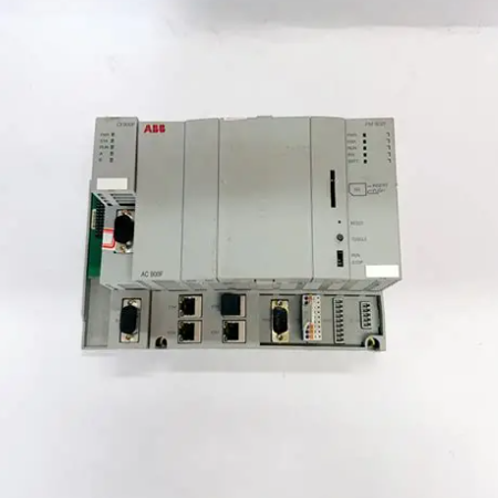
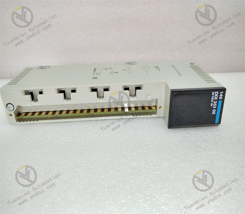
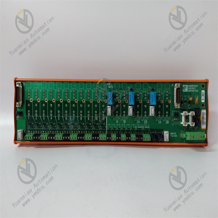
Description
Technical Specifications Functional Features: As a relay output module, it can receive signals from the control system and control the start/stop or status switching of external devices such as motors, valves, and indicator lights through the closing or opening of the relay contacts. Number of Channels: It usually has multiple relay output channels. The specific number varies depending on the model and configuration, which can meet the requirements for multi-channel output control in different industrial control scenarios. Contact Capacity: The relay contacts have a certain load capacity and can withstand a certain amount of current and voltage. Common contact capacities may include the maximum switchable current (such as 5A, 10A, etc.) and the maximum voltage (such as 250V AC or 30V DC, etc.) to ensure reliable control of external loads. Input Signals: It can receive different types of input signals, such as digital signals, which are usually input into the module in the form of standard level signals (such as TTL level) so that the module can control the action of the relay according to the input signals. Power Requirements: Generally, it requires a stable DC or AC power supply. Common power supply voltages may be 24V DC or 110V/220V AC, etc., depending on the design and specifications of the module. Operating Temperature Range: It can usually operate stably within a certain temperature range, such as approximately -20°C to +70°C, to adapt to different industrial environmental conditions.
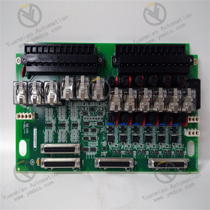
Features and Advantages High Reliability: By using high-quality relays and electronic components and going through strict testing and verification, it can operate stably for a long time in an industrial environment, reducing the probability of failures. Easy Integration: It can be conveniently integrated into GE's Mark VIe control system or other compatible industrial automation systems, working in coordination with other modules and devices to achieve complex control logic. Isolation Protection: The relay output has an electrical isolation function, which can effectively isolate the electrical connection between the control circuit and the controlled device, prevent the mutual influence of electrical interference and equipment failures, and improve the safety and stability of the system. Flexible Configuration: According to the actual application requirements, the output modes of the relays (such as normally open and normally closed contacts) and the action logic can be flexibly configured to meet the personalized control requirements of different users. Application Areas Power Industry: It is widely used in the control of generator sets in power plants, the control of electrical equipment in substations, etc., and is used to control the excitation system of generators, the opening and closing operations of circuit breakers, the display of various signal indicator lights, etc. Petrochemical Industry: It can be used for the control of various equipment in the petrochemical production process, such as the opening and closing control of valves, the start and stop control of pumps, the adjustment of pipeline pressure and flow rate, etc., to ensure the safe and stable operation of the production process. Industrial Automation Production Lines: In industrial automation production lines such as automobile manufacturing, mechanical processing, and electronics manufacturing, it is used to control various actuators on the production line to achieve the automation and precise control of the production process. Process Control: In the process control of industries such as chemical, pharmaceutical, and food processing, it monitors and adjusts the control of process parameters and the operating status of equipment to ensure product quality and production efficiency.
Common Faults and Solutions Relay Not Operating Possible Causes: Abnormal input signals (such as the signal not being correctly transmitted to the module, the signal level not meeting the requirements, etc.), power supply problems (such as insufficient power supply voltage, power interruption, etc.), faults in the relay itself (such as damaged contacts, burned-out coils, etc.). Solutions: Check the input signal circuit to ensure that the signal can be correctly transmitted to the module, and use tools such as a multimeter to measure whether the input signal level is normal; Check the power supply to ensure that the power supply voltage is within the rated range of the module and the power connection is normal; If a relay fault is suspected, use a multimeter to measure the resistance value of the relay coil to determine whether the coil is burned out. If the contacts are damaged, the relay needs to be replaced. Poor Contact of Contacts Possible Causes: Contact wear caused by long-term use, dirt or oxidation on the contact surface, contact overheating caused by excessive load, etc. Solutions: Regularly check the status of the relay contacts. If there is wear or oxidation, sandpaper or a special contact cleaner can be used for treatment; Ensure that the load is within the rated capacity range of the relay contacts to avoid overloading operation; If the contacts are severely damaged, the relay should be replaced in a timely manner. Module Communication Fault (if there is a communication function) Possible Causes: Poor connection of the communication cable, incorrect setting of the communication protocol, damage to the module communication interface, etc. Solutions: Check whether the connection of the communication cable is firm and whether there is any damage or poor contact; Confirm whether the communication protocol settings are consistent with those of other devices, such as baud rate, data bits, stop bits, etc.; If the module communication interface is damaged, professional maintenance personnel need to be contacted for inspection or replacement of the module.

Installation
Select Installation Location
Installation Methods
Power Connection
External Device Connection
Configuration
Hardware Inspection
Initial Setup
Programming and Function Settings
Select Programming Software
Create a Project
Write Control Logic
Configure Output Channels
Operation and Monitoring
Start Operation
Real-Time Monitoring
Fault Diagnosis and Handling