Description
1. Product Overview
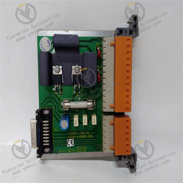
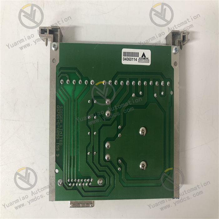
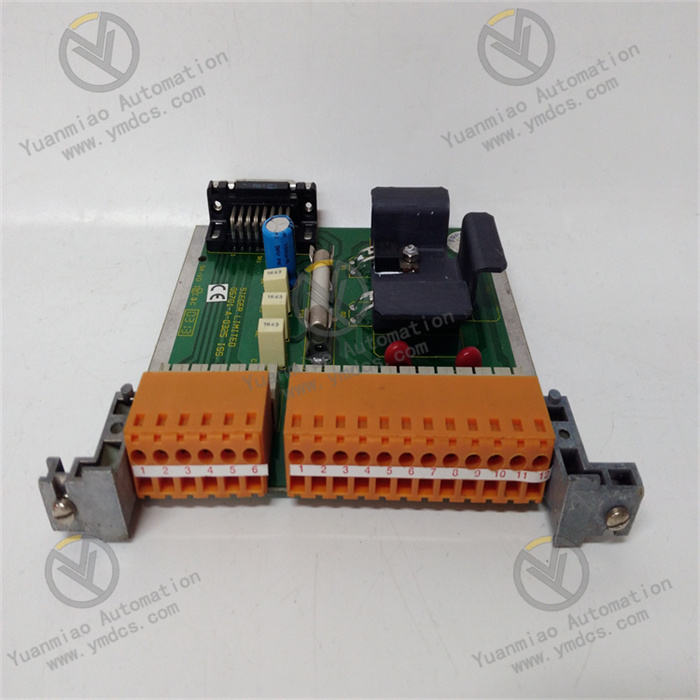
The Honeywell 05701‑A‑0325 is a flame detector amplifier module within Honeywell’s 05701 series for industrial flame detection. It is widely deployed in thermal‑power, petrochemical, chemical, gas‑fired heating boiler and gas‑turbine burner flame‑monitoring protection systems, serving as a critical front‑end signal‑processing unit for boiler FSSS (Furnace Safety Supervision System).
Matched with Honeywell compatible ultraviolet flame probes, this module collects ultraviolet optical signals from burner flames and performs signal amplification, filtering, discrimination and flame‑intensity calculation. It distinguishes genuine flames from furnace background radiation and flame interference, and outputs discrete flame‑status signals as well as analog flame‑intensity signals. These signals are fed into the FSSS to judge flame presence / flame loss and participate in boiler combustion interlocks and flame‑out protection.
Housed in an independent metal enclosure, the module is designed for cabinet DIN‑rail mounting. Its output signals are sent to DCS/FSSS systems for combustion‑condition monitoring and trip‑logic execution. Subjected to high‑temperature aging, EMC electromagnetic‑compatibility, vibration‑shock and other reliability tests, it withstands high temperature, dust and heavy electromagnetic interference inside boiler control cabinets and supports long‑term continuous operation. It is a commonly‑used spare part for maintenance, component replacement and technical retrofits of industrial‑boiler FSSS systems.
2. Functional Features
2.1 UV Flame Signal Acquisition and Amplification
Receives weak induced UV optical signals from ultraviolet flame probes and applies multi‑stage amplification to extract characteristic flame signals, enabling reliable detection under low‑load and weak‑flame burner operating conditions.
2.2 Flame‑Signal Discrimination with Anti‑False‑Flame Interference
Built‑in signal‑filtering and flame‑spectrum‑discrimination circuits differentiate real combustion flames from high‑temperature furnace background radiation, furnace light reflection and cross‑illumination from adjacent burners, preventing false no‑flame alarms and false‑flame misjudgments.
2.3 Dual‑Type Signal Output
Provides dry‑contact discrete signals indicating flame status for FSSS protection logic; simultaneously outputs analog flame‑intensity signals for real‑time flame‑strength visualization on DCS HMI screens to facilitate operator supervision of combustion conditions.
2.4 Local Status LED Indicators
On‑board LED indicators clearly display power supply health, valid flame detection and fault‑alarm status. On‑site operators can quickly evaluate module status without relying on upper‑level host systems.
2.5 On‑Board Self‑Diagnosis and Fault Alarm
Continuously monitors power‑supply circuits, open‑circuit / short‑circuit faults of probe wiring, and signal‑acquisition channel health. Upon detection of wiring anomalies or hardware failures, fault‑alarm signals are transmitted to the FSSS to prevent protection‑rejection events caused by detection‑loop failures.
2.6 Modular DIN‑Rail Mounting
Standard DIN‑rail form factor enables simple installation and removal for flexible cabinet layout. The metal‑shielded enclosure mitigates electromagnetic interference generated by high‑power boiler‑site equipment.
2.7 Wide‑Range Power Supply and Robust Environmental Adaptability
Supports industrial wide‑range DC power input to accommodate minor on‑site supply‑voltage fluctuations. With vibration resistance and wide‑temperature operation capability, it fits harsh industrial environments such as power‑plant and chemical‑process boilers.
3. Technical Specifications
3.1 Core Compatibility Parameters
| Item | Specification |
|---|---|
| Model | 05701‑A‑0325 |
| Brand | Honeywell |
| Product Series | 05701‑Series Flame‑Detection Amplifier |
| Module Type | Flame Detector Amplifier Module |
| Compatible Probes | Honeywell ultraviolet flame detectors |
| Mounting Method | DIN‑rail mounting |
| Core Interfaces | Flame‑probe signal input, discrete output, analog intensity output, power‑supply terminals |
| Core Functions | UV flame‑signal amplification, flame discrimination, flame‑intensity conversion, wiring‑fault diagnosis, flame‑status output |
| Typical Applications | FSSS furnace‑safety supervision systems for utility‑station boilers and industrial gas‑fired / oil‑fired boilers; burner flame monitoring and flame‑out protection |
3.2 Electrical Performance Parameters
| Item | Specification |
|---|---|
| Detection Principle | UV‑spectrum flame detection |
| Input Signal | Weak induced optical signals from ultraviolet flame probes |
| Output Signals | Dry‑contact discrete flame‑status signals; analog flame‑intensity signals |
| Power Supply | Industrial DC power supply |
| Diagnostic Functions | Self‑testing for probe open‑circuit, probe short‑circuit and module power‑supply faults; fault‑alarm output; front‑panel LED status indication |
| EMC Performance | Complies with industrial IEC electromagnetic‑compatibility standards; provides immunity against interference from frequency converters and high‑power motors |
3.3 Environmental and Physical Parameters
| Item | Specification |
|---|---|
| Operating Temperature | Wide‑temperature range for industrial cabinet deployment |
| Storage Temperature | Wide‑temperature tolerance for spare‑part storage and transportation |
| Operating Humidity | 5 % ~ 95 % RH, non‑condensing |
| Environmental Resistance | Dust‑proof, vibration‑resistant, electromagnetically‑shielded; suitable for power‑plant boiler cabinet environments |
| Compliance Standards | Safety‑oriented design for boiler FSSS applications; complies with industrial combustion‑safety specifications |
| Mechanical Construction | Metal‑shielded enclosure, modular DIN‑rail housing |
4. Hardware Configuration & Structural Advantages
4.1 Core Hardware Configuration
The Honeywell 05701‑A‑0325 consists mainly of a pre‑amplifier circuit, UV‑signal filtering‑and‑discrimination unit, flame‑intensity conversion circuit, fault‑detection loop, output relay / analog‑output circuit, power‑supply‑regulation unit, LED status indicators, metal‑shielded enclosure and terminal block.
UV optical signals captured by the flame probe enter the amplifier input terminals. The pre‑amplifier circuit amplifies weak input signals; the filtering‑and‑discrimination unit extracts characteristic flame spectra and rejects furnace‑background noise. The flame‑intensity‑conversion circuit converts flame signals into analog outputs, while driving relays to produce discrete flame‑status contacts. The fault‑detection loop continuously monitors probe‑cable continuity and module power‑supply status. The power‑supply unit stabilizes external input power for all internal circuits. The metal enclosure delivers electromagnetic shielding to suppress noise induced by high‑power on‑site equipment.
4.2 Structural & Engineering Advantages
DIN‑rail clip‑on mounting enables fast installation and removal. Spare‑part replacement can be completed without extensive wiring modifications, simplifying maintenance work. The metal‑shielded enclosure delivers high anti‑interference performance for environments populated by high‑power fans and frequency converters typical of boiler plants.
Integrated flame discrimination plus wiring‑fault diagnosis lowers the risk of FSSS‑system protection failure. Standardized output interfaces support direct connection to mainstream FSSS/DCS platforms. Excellent interoperability with other Honeywell flame‑detection components and mature spare‑part‑maintenance workflows make it widely adopted for servicing and retrofitting legacy boiler FSSS installations.
5. Working Principle
Working sequence for 05701‑A‑0325: UV optical signals captured by the burner‑mounted flame probe → amplifier input terminals → pre‑amplification → spectral filtering and flame discrimination → flame‑intensity conversion and flame‑status evaluation → analog + discrete outputs transmitted to FSSS / DCS; continuous loop self‑diagnosis runs in parallel.
Upon burner ignition, the ultraviolet flame probe senses UV radiation emitted by the flame and converts it into weak electrical signals sent to the 05701‑A‑0325 amplifier. The module applies multi‑stage signal amplification, while filtering circuits reject non‑flame interference such as furnace infrared background radiation and ambient stray light. The discrimination unit evaluates UV‑signal characteristics to confirm valid flame presence.
When a valid flame is confirmed, the module illuminates its flame‑status LED, closes the dry‑contact relay and outputs an analog signal proportional to flame intensity. When the flame extinguishes, input signals vanish and the module asserts the no‑flame status. The FSSS receives these status signals and executes flame‑out‑protection interlock logic. The module continuously monitors probe‑cable open‑circuit and short‑circuit conditions. When wiring damage is detected, a fault alarm is triggered to prompt maintenance and prevent detection‑loop failure.
6. Common Faults and Troubleshooting
6.1 Valid flame present, but module reports no‑flame; loss of flame signal
| Possible Cause | Troubleshooting Method | Remedial Action |
|---|---|---|
| Flame‑probe lens fouling by dust, reduced light transmittance | Inspect probe lens for dust and oil contamination during shutdown | Clean UV lens, purge probe assembly, implement dust‑prevention measures |
| Aging or open‑circuit in signal cable between probe and amplifier | Power off, test cable continuity; inspect terminal tightness | Repair or replace signal cable; retighten terminals |
| Degradation of amplifier pre‑amplifier circuit | Perform comparative test with a spare 05701‑A‑0325 module | Replace flame‑detector amplifier module |
| Misaligned probe mounting; flame outside probe field‑of‑view | Verify probe mounting angle; confirm optical axis targets the actual flame | Adjust probe mounting angle and field‑of‑view alignment |
6.2 No flame present, but module falsely reports flame (false‑flame indication)
| Possible Cause | Troubleshooting Method | Remedial Action |
|---|---|---|
| Furnace background thermal radiation or cross‑illumination from adjacent burners | Inspect probe field‑of‑view for stray light from neighbouring burners | Reposition probe; install light‑baffle shields; optimize field‑of‑view |
| Drift of discrimination‑circuit parameters, degraded anti‑interference performance | Compare performance against other channels under identical operating conditions | Replace 05701‑A‑0325 amplifier module |
| Improper shielding‑cable grounding, coupled interference noise | Check single‑point grounding of cable shield; separate signal cables from power cables | Correct shield‑grounding practice; physically segregate signal and power wiring |
6.3 No power‑supply LED upon power‑up; module inoperative
| Possible Cause | Troubleshooting Method | Remedial Action |
|---|---|---|
| Loss of external supply voltage; blown fuse | Measure voltage at module power terminals; inspect fuses in supply circuit | Restore power, replace blown fuse; trace and resolve short‑circuit root‑cause |
| Loose power terminals, poor electrical contact | Power off, inspect terminals for oxidation | Retighten power‑wiring terminals |
| Internal failure of module power‑regulation circuit | Supply voltage normal at terminals, yet no LED; test with spare module | Replace 05701‑A‑0325 amplifier module |
6.4 Repeated probe‑wiring‑fault alarms
| Possible Cause | Troubleshooting Method | Remedial Action |
|---|---|---|
| Damaged probe‑cable insulation, intermittent short‑circuit / leakage | Measure cable insulation resistance; locate damaged cable segments | Replace signal cable; route cable away from high‑temperature sources; add mechanical protection |
| Oxidized terminals, unstable contact resistance | Inspect and clean corroded terminals on module and probe sides | Polish contact surfaces, retighten connections, apply terminal protection measures |
| Degradation of on‑board wiring‑diagnosis circuitry | Cable passes insulation tests but fault alarms persist | Replace 05701‑A‑0325 amplifier module |