Description
1. Overview
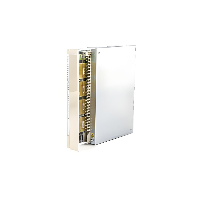
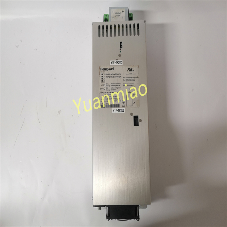
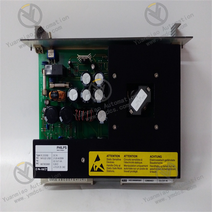
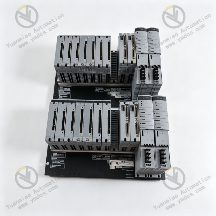
Yokogawa PW482‑50 S2 is a high‑performance redundant power supply module dedicated for Yokogawa ProSafe‑RS Safety Instrumented System (SIS). As a standard power‑supply hardware of Yokogawa PW482 series, it provides stable and clean DC24V operating power for the complete SIS and DCS process‑control system cabinets.
Designed for 24‑hour non‑stop continuous operation in process industries, this module features high conversion efficiency, stable wide‑temperature operation, multiple electrical protections and redundant fault‑tolerant power supply. It serves as the core power‑supply unit for Yokogawa control‑system cabinets. PW482‑50 S2 is the basic standard version without explosion‑proof certification. It natively supports cabinet redundant parallel power‑supply architecture and allows on‑line hot‑swap replacement without system shutdown.
Widely adopted for maintenance replacement, system expansion and legacy‑hardware upgrade of control systems under high‑risk conditions such as petroleum, chemical, natural‑gas and power industries. It is an original‑equipment dedicated spare part with no universal alternative.
2. Functions and Features
2.1 Core Functions
System Regulated Power Output: Precisely converts industrial AC220V mains into stable DC24V power. Supplies clean regulated power to cabinet CPU controllers, I/O boards, communication modules and terminal loops, preventing system reset, data abnormality and module misoperation caused by voltage fluctuation.
Redundant Parallel Fault‑tolerant Power Supply: Supports multi‑module redundant parallel operation with automatic load‑current sharing. When one power module fails, shuts down or is swapped, remaining modules take over full load seamlessly with no power interruption or voltage drop to ensure non‑stop system operation.
Comprehensive Electrical Protection: Built‑in over‑voltage, under‑voltage, over‑current, short‑circuit and over‑temperature protections. It responds rapidly to electrical anomalies, locks output automatically and isolates faults to avoid load‑equipment burnout and power‑loop damage.
High‑efficiency Power Conversion: Adopts high‑frequency switching‑power architecture with up to 96% conversion efficiency. Low energy consumption and low heat generation greatly reduce cabinet heat‑dissipation burden and operating energy cost, suitable for long‑term continuous operation.
On‑line Maintenance with Hot‑swap: Supports on‑line hot‑swap replacement under loaded conditions. Maintenance can be performed without shutdown, power‑off or disturbance to system configuration and control logic, eliminating unplanned outage risks.
Operating‑status Self‑diagnosis and Alarm: Real‑time monitoring of input voltage, output voltage, load current, module temperature and operating conditions. Status LEDs indicate working conditions intuitively with accurate fault alarms for fast localization and troubleshooting.
2.2 Product Features
High‑reliability Industrial‑grade Stability: Designed for continuous industrial‑control operation. Tolerates voltage fluctuation and load impulse with low output ripple and high stability, complying with power‑supply standards for high‑reliability SIS and DCS control systems.
Wide‑temperature Environmental Adaptability: Extra‑wide operating‑temperature range withstands both cold and high‑temperature cabinet conditions. Resists humidity, dust and vibration for harsh industrial field environments.
Low‑noise & Low‑power Operation: Optimized thermal and circuit design delivers low noise and low heat output. Compared with conventional power modules, it achieves lower energy consumption, longer service life and reduced maintenance cost.
Full Original‑equipment Compatibility: Standard Yokogawa cabinet slot‑mount form‑factor. Pin definition, electrical parameters and communication interfaces are fully compatible with ProSafe‑RS and full‑range Yokogawa DCS systems. Plug‑and‑play without commissioning or calibration upon replacement.
Long‑service‑life Quality Assurance: Constructed with premium industrial‑grade components for high overall stability and extremely low failure rate. Backed by standard original long‑term warranty to meet long‑lifespan industrial‑equipment requirements.
3. Specifications
| Parameter Item | Technical Specification |
|---|---|
| Model | PW482‑50 S2 |
| Device Type | Redundant Power‑supply Module for Yokogawa ProSafe‑RS / DCS Systems |
| Input Voltage | AC 220~240V industrial mains |
| Output Voltage | Regulated DC24V standard output |
| Rated Power | 480W high‑power output |
| Conversion Efficiency | Up to 96%, high‑efficiency energy‑saving |
| Redundancy Mode | Multi‑module parallel redundancy, load sharing, bumpless switching |
| Protection Mechanism | Comprehensive protections: over‑voltage, under‑voltage, over‑current, short‑circuit, over‑temperature |
| Operating Temperature | -20℃ ~ +70℃ (industrial wide‑temperature grade) |
| Ambient Humidity | 5%~95%RH, non‑condensing |
| Installation Method | Standard cabinet slot‑mount installation, hot‑swap supported |
| Explosion‑proof Rating | Standard version without explosion‑proof certification |
| Applicable Systems | Yokogawa ProSafe‑RS SIS, Yokogawa DCS process‑control systems |
4. Working Principle
The Yokogawa PW482‑50 S2 power module implements closed‑loop regulated workflow: AC Input → Rectification & Filtering → High‑frequency Transformer Conversion → Regulated Output → Intelligent Monitoring & Protection.
After industrial AC220V mains enters the module, pre‑filter and rectifier circuits suppress grid noise and surge interference and convert AC into raw DC voltage. High‑frequency switching circuits and isolation transformers perform precise voltage conversion and galvanic isolation. Post‑regulation and filtering circuits finally deliver clean and stable DC24V power for various cabinet control hardware.
Under multi‑module redundant parallel operation, each PW482‑50 S2 outputs power evenly via load‑sharing mechanism. If one module fails, powers off or undergoes hot‑swap, load is switched over seamlessly without voltage drop or power loss.
High‑precision on‑board monitoring chips continuously sample input/output voltage, load current and internal module temperature. Once over‑voltage, over‑current, short‑circuit or overtemperature is detected, protection lockout is triggered immediately, faulty output is cut off and fault LED is activated. Fault points are isolated to protect downstream control hardware and sustain stable power supply.
5. Application Scenarios
Chemical SIS Safety Instrumented Systems: Main power‑supply unit for ProSafe‑RS safety‑system cabinets in refineries, fine‑chemical plants and coal‑chemical facilities. Supplies uninterrupted regulated power for ESD emergency shutdown, process interlock and safety‑monitoring hardware to guarantee reliable execution of safety interlocks under high‑risk conditions.
Oil & Gas Industry Control Systems: Cabinet power supply for automation systems in oilfields, gas fields, LNG plants and long‑distance pipelines. Adapts to field conditions with wide temperature range, heavy dust and strong interference to ensure 24‑hour stable control‑system operation.
Power‑plant Industrial Automation Systems: Cabinet power supply for plant auxiliary‑control, unit process‑control and thermal‑monitoring systems. Meets continuous production requirements of power plants and prevents unit anomalies induced by power‑supply fluctuation.
General‑purpose Industrial DCS Control Systems: Core power‑supply module for various process‑industry DCS automation systems. Stabilizes power for controllers, I/O and communication equipment and avoids system off‑line and data loss caused by power failure.
Legacy‑system Maintenance & Retrofit: Fully compatible with older PW482‑series power modules. Faulty or aged power units can be directly replaced without modifying cabinet wiring, power loops or system configuration for fast equipment repair and system expansion.
6. Common Faults and Troubleshooting
6.1 No Module Output, System Power Loss, Power Indicator Off
Fault Causes: Loss of upstream AC220V input; blown input fuse; internal circuit damage; poor contact in power loops.
Solutions: Inspect cabinet AC input voltage, circuit‑breaker and fuse status to eliminate upstream supply faults; check contact conditions of module terminals and slots; power‑cycle and reset the module for retest; replace original PW482‑50 S2 module if internal hardware is damaged.
6.2 Unstable Output Voltage, Frequent System Power‑cycling, Module Alarm
Fault Causes: Excessive mains‑voltage fluctuation; aged regulation circuitry; load overload; uneven load distribution among redundant modules; poor loop contact.
Solutions: Monitor mains input voltage and resolve grid anomalies; calculate total cabinet load and avoid operation above rated power; verify load‑sharing status of redundant modules and calibrate power‑supply parameters; replace spare module when regulation performance degrades.
6.3 Overtemperature Alarm, De‑rated Output at High Temperature
Fault Causes: Poor cabinet heat dissipation; blocked air duct; excessive dust accumulation; high ambient temperature; long‑term full‑load module operation.
Solutions: Clean cabinet air duct and module heat‑sink dust; check cabinet fan operation; improve room ventilation and lower ambient temperature; reduce load burden on individual modules; replace original module if overtemperature alarms recur indicating module aging.
6.4 Frequent Short‑circuit / Over‑current Protection, Output Locked
Fault Causes: Short‑circuit in downstream I/O loops; equipment leakage; defective load devices; drifted module over‑current protection parameters.
Solutions: Troubleshoot downstream cabinet load loops section‑by‑section, isolate short‑circuited or leakage‑faulty equipment; reset module protection state to restore power supply; replace module if protections still trigger after eliminating external‑load faults.
6.5 Redundant Parallel Failure, Single‑module Heavy Load, Uneven Load Sharing
Fault Causes: Mismatched module revisions; abnormal parallel‑communication; inconsistent parameters; poor slot contact leading to load‑sharing failure.
Solutions: Verify consistency of model and firmware revision among redundant power modules; clean module slots and terminals, re‑insert and fasten securely; reset redundant power‑supply configuration; replace faulty module if load‑sharing function cannot be recovered.