Description
1. Product Overview
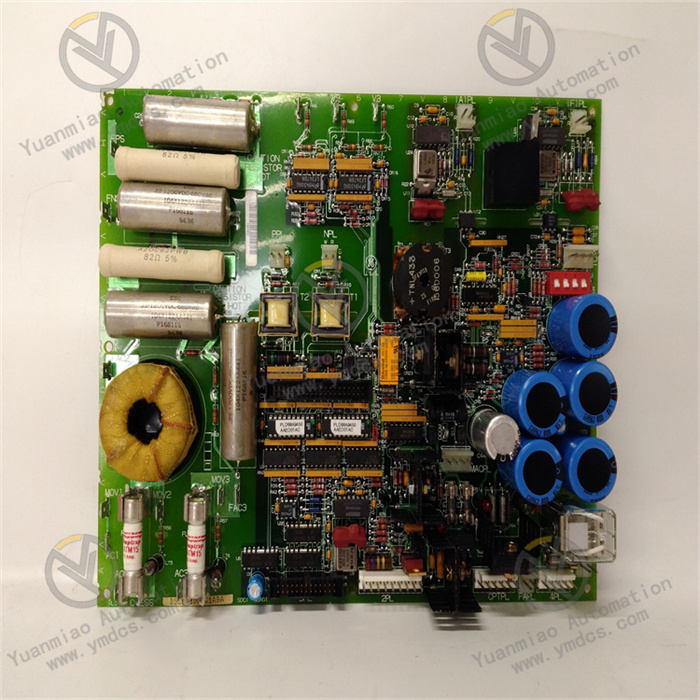
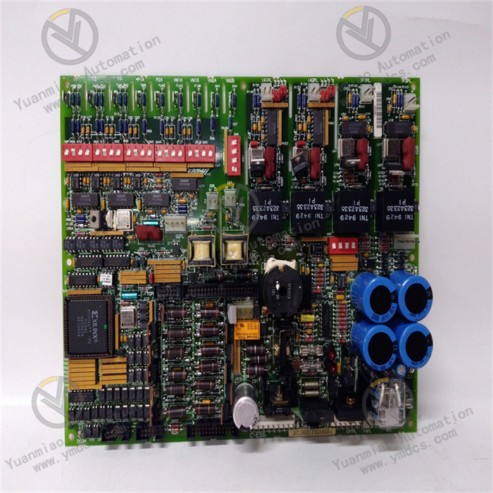
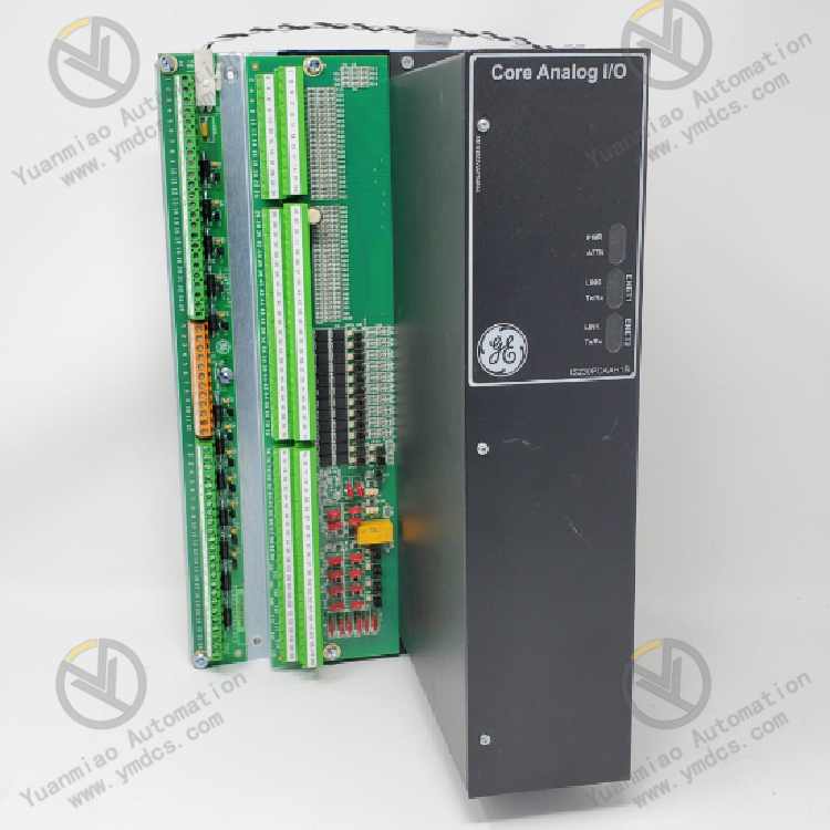
Full Model: IS230PCAAH1A
Manufacturer: GE General Electric
Product Series: Mark VIe Speedtronic Turbine Control System I/O Module Series
Product Name: Multi-Function Core Analog I/O Module, General Process Control Acquisition & Output Card
Product Positioning
IS230PCAAH1A is a high-end multi-function core analog I/O module for GE Mark VIe gas turbine and steam turbine control systems. It serves as the core interaction unit for process parameter acquisition and actuator regulation of turbine units. Integrated with multi-type signal acquisition, analog output, condition monitoring and servo drive functions, this module is the critical hardware for collecting process parameters such as unit temperature, pressure, displacement, vibration and flow, as well as closed-loop regulation of valves and servo mechanisms. Designed with power-plant-grade rugged industrial hardware and equipped with a high-precision 24-bit ADC sampling architecture, it adapts to harsh operating conditions including sustained high temperature, mechanical vibration and strong electromagnetic interference in thermal power combined cycle plants and gas turbine power facilities. It is widely used for new unit matching, I/O module replacement in legacy systems, control system expansion and industrial control technical retrofits, featuring excellent versatility and system compatibility.
Core Functions
This module undertakes two core responsibilities: full-category process signal acquisition and analog regulation output for turbine units. It supports unified acquisition and processing of various field signals including thermocouple temperature signals, standard 4-20mA current signals, LVDT displacement signals, seismic vibration signals and high-frequency pulse signals. Meanwhile, it outputs high-precision analog control signals to drive servo coils, regulating valves and actuators. It performs real-time high-precision sampling, filtering calibration and data conversion of key parameters such as unit temperature, pressure, displacement, vibration and load conditions. It provides original accurate data for unit closed-loop PID regulation, steady-state condition control, over-limit alarm, interlock protection and fault tracing. In addition, it outputs continuous regulation commands according to main controller instructions to realize precise position control of gas turbine inlet valves, steam control valves and servo actuators. It ensures smooth unit startup and shutdown, linearly stable load regulation and controllable equipment operating conditions, and avoids operational risks including parameter runaway, actuator malfunction and excessive condition fluctuation.
Compatible Systems
Fully compatible with the complete architecture of GE Mark VIe Speedtronic turbine control systems, it matches the main control framework of gas-steam combined cycle units, simple-cycle gas turbine units, condensing steam turbine units and industrial drive turbine units. It seamlessly cooperates with system main control processors, speed measurement boards, digital I/O boards, communication modules and power supply modules. Natively supporting dual IONet bus protocols, it complies with original backplane bus specifications, cabinet installation standards and underlying control logic. It can be matched with TCAT terminal boards and JGPA adapter boards for signal extension and shielding termination. Backward-compatible replacement between new and old systems is available without extensive modification of programs and wiring. It fits full engineering scenarios including new unit commissioning, aged module replacement, system upgrading & expansion and industrial control technical transformation.
Application Scenarios
It is widely deployed in large thermal power plants, gas combined cycle power stations, cogeneration power plants, oil & gas chemical power workshops and other facilities, dedicated to process parameter acquisition and actuator regulation for gas turbines, steam turbines and large compressor units. Capable of long-term operation under harsh cabinet conditions in power plants such as high temperature, dust, mechanical vibration and strong electromagnetic interference, it performs core tasks including unit temperature monitoring, pressure & flow acquisition, valve position feedback, vibration monitoring, servo actuator regulation and closed-loop process control. It is an indispensable core I/O unit for process control and equipment condition monitoring of turbine machinery.
2. Technical Features
Multi-Signal Compatible Acquisition with High Integration
The module highly integrates multi-type signal processing circuits. A single board supports thermocouple temperature measurement, 4-20mA current acquisition, LVDT displacement detection, seismic vibration measurement, high-frequency pulse input and servo coil drive output. It completes full-range analog signal interaction of the unit without multiple single-function boards, greatly simplifying cabinet wiring and hardware architecture, and reducing equipment failure rate and maintenance cost. Signal channels can be flexibly configured to adapt to different field sensors and actuators, satisfying diverse process control requirements of turbine units.
24-bit High-Precision Sampling with Superior Measurement Accuracy
Adopting 24-bit high-precision ADC sampling chips, the system acquisition accuracy reaches ±0.05% with ultra-high sampling resolution, enabling precise capture of subtle variations in unit temperature, pressure, displacement and vibration. Combined with multi-stage digital calibration algorithms and linear compensation mechanisms, signal drift, sampling deviation and linear distortion are effectively eliminated. Data remains stable and accurate across the full measurement range, meeting strict technical requirements of large turbine units for precise regulation, over-limit protection and accurate condition evaluation.
High-Speed Bus Communication with Excellent Real-Time Performance
Equipped with dual 10/100Mbps IONet high-speed Ethernet buses supporting redundant dual-link parallel transmission. The data refresh cycle is ≤100ms, enabling millisecond-level upload of acquired data and real-time distribution of control commands. The bus features large throughput and ultra-low packet loss rate. It supports 1ms-class SOE sequence-of-event recording to accurately capture instantaneous abnormal conditions and fault time sequences, providing precise time-series data support for fault tracing, condition analysis and system optimization, and guaranteeing response speed and control real-time performance during dynamic unit regulation.
Industrial Wide-Temperature Rugged Design with Strong Environmental Adaptability
Constructed with power-plant-grade reinforced PCB and full industrial wide-temperature components, treated with moisture-proof, dust-proof, shock-proof and anti-corrosion processes. It supports continuous long-term operation from -30℃ to +65℃, and withstands 5g RMS vibration and 30g transient impact. It perfectly adapts to 24/7 nonstop operation, equipment vibration and temperature & humidity fluctuations in power plants, with no parameter drift, channel failure or signal distortion during long-term operation.
Comprehensive Self-Diagnosis and Fault Identification for High Operational Reliability
Built-in full-range hardware self-test, channel status monitoring, signal break detection and data verification mechanisms continuously monitor board power supply, chip operation, channel signal status and bus link integrity. It actively and accurately identifies hidden risks including sensor disconnection, line short circuit, signal over-range, channel abnormality, bus interruption and hardware failure. Fault codes and event logs are uploaded in real time to help maintenance personnel quickly locate faults and eliminate potential hazards, preventing inaccurate unit regulation, false protection and condition runaway caused by abnormal signals.
Hot-Swappable Modular Design for Convenient Maintenance & Replacement
Adopting standardized pluggable modular structure of Mark VIe series with uniform dimensions and interfaces, the module supports hot-swap replacement without unit shutdown or power cut. It supports power-on comprehensive self-test, online parameter configuration and non-stop channel debugging & status monitoring. Failed legacy modules can be replaced in-situ without modifying system programs, control logic or wiring layout, greatly shortening maintenance duration and reducing power plant outage losses and maintenance costs.
Multiple Electrical Protection Circuits with Outstanding Anti-Interference Performance
Integrated circuits for electrical isolation, electromagnetic shielding, surge suppression, electrostatic protection and electrical fast transient pulse suppression, together with dedicated signal filtering and voltage stabilization circuits. It effectively resists complex electromagnetic disturbances in power plants originating from variable frequency drives, high-voltage radiation, line surges, voltage fluctuations and electrostatic discharge. Signal jitter, data hopping and sampling distortion under strong electromagnetic environments are avoided to ensure stable channel signals and reliable control logic.
3. Specification Parameters
| Item | Parameter |
|---|---|
| Model | IS230PCAAH1A |
| Manufacturer | GE General Electric |
| Product Series | Mark VIe Speedtronic Turbine Control System I/O Module |
| Equipment Type | Multi-Function Core Analog Input & Output Module, General Process Control I/O Card |
| Applicable Equipment | Gas Turbine, Steam Turbine, Large Industrial Compressor, Turbine Machinery |
| Applicable System | Complete GE Mark VIe Speedtronic Turbine Control System |
| Core Functions | Multi-type analog signal acquisition, LVDT displacement detection, vibration/temperature/pressure monitoring, high-frequency pulse processing, servo coil drive, analog regulation output, channel self-diagnosis, SOE event recording, data upload |
| Sampling Accuracy | 24-bit high-precision ADC sampling, system accuracy ±0.05% |
| Supported Signal Types | Thermocouple signal, 4-20mA current signal, LVDT displacement signal, seismic vibration signal, high-frequency pulse signal, servo drive output |
| Channel Configuration | Multi-channel integrated, configurable for all analog signal types |
| Output Specifications | 0~10VDC analog output, maximum single-channel output current: 160mA |
| Power Supply | DC 18~30V wide-range input, standard 24VDC system power supply |
| Communication Bus | Dual 10/100Mbps redundant IONet Ethernet bus |
| Data Refresh Cycle | ≤100ms |
| Event Recording Accuracy | 1ms-class SOE sequence-of-event recording |
| Matching Accessories | JGPA power connector, 68-pin cable, TCAT terminal board |
| Operating Temperature | -30℃~+65℃ |
| Storage Temperature | -40℃~+85℃ |
| Ambient Humidity | 5%~95%RH, non-condensing, suitable for power plant cabinet environment |
| Mechanical Performance | Vibration resistance: 5g RMS (10~2000Hz); Shock resistance: 30g/11ms |
| Electrical Features | Electrical isolation, electromagnetic shielding, surge protection, multi-stage signal filtering, high immunity to electromagnetic interference |
| Mechanical Features | Standard rack-mount pluggable module, hot-swappable, compact structure, high interchangeability |
| O&M Features | Power-on comprehensive self-test, online configuration & debugging, fault code reporting, in-situ hot replacement, non-stop debugging |
| Product Characteristics | High integration, precise sampling, fast response, redundant stability, strong anti-interference, wide-temperature endurance, complete self-diagnosis, easy maintenance |
4. Working Principle
4.1 Power-On Initialization and Full-Range Hardware Self-Test
After receiving 24VDC industrial power supply, the module automatically completes hardware initialization, driver loading, bus protocol matching, channel parameter calibration and full-range self-test. It sequentially inspects ADC sampling units, signal processing circuits, analog output loops, communication ports, power circuits and self-test logic to detect hardware damage, channel faults, bus disconnection, parameter disorder and circuit failures. Once self-test passes, configuration parameters and channel settings from the main control system are synchronized automatically. Signal range calibration and channel function definition are completed, and the module enters real-time acquisition and regulation operation mode.
4.2 Multi-Type Field Signal Acquisition and Precision Processing
During unit operation, the module receives raw signals transmitted by field sensors, including thermocouple temperature signals, 4-20mA pressure & flow signals, LVDT valve position signals, vibration monitoring signals and high-frequency pulse signals. Built-in multi-stage hardware filtering and software noise reduction algorithms suppress electromagnetic interference, line clutter, signal jitter and waveform distortion. Raw signals are conditioned, error-corrected, linearly compensated and range-converted. Based on the 24-bit high-precision ADC architecture, analog signals are accurately converted into digital operating data. Invalid abnormal data is filtered to form stable standardized operating data, providing accurate data sources for system computation and regulation.
4.3 Data Upload and Coordinated Calculation with Main Control Logic
Via dual redundant IONet high-speed buses, multi-dimensional operating data including temperature, pressure, displacement, vibration and flow is uploaded to the Mark VIe main control processor in millisecond scale. Relying on uploaded data, the main controller executes core calculations such as unit PID load regulation, closed-loop valve position control, steady-state temperature & pressure tuning, over-limit condition judgment and vibration fault analysis. Dynamic precise regulation commands are generated according to real-time unit conditions and sent to this module for output. A closed-loop control logic of “Acquisition — Upload — Calculation — Regulation” is formed to maintain stable and controllable unit operating conditions.
4.4 Precise Analog Output and Actuator Regulation
Upon receiving regulation commands from the main control system, the module outputs standard 0~10VDC analog control signals via high-precision DAC conversion circuits to drive servo coils, pneumatic control valves, hydraulic actuators and other field equipment. The output signals feature high linearity and stability, precisely matching requirements of valve opening and actuator stroke adjustment. Stepless accurate regulation is realized for gas turbine inlet valves, steam control valves, bypass valves and other equipment. It ensures smooth operation during unit startup, loading, steady-state operation and unloading without overshoot, delay or oscillation in regulation.
4.5 Real-Time Fault Self-Diagnosis and Abnormal Condition Protection
The module continuously activates four-layer self-diagnosis covering hardware, channels, signals and buses to monitor operating status of acquisition channels, output loops, power supply and bus links. It accurately identifies faults such as sensor disconnection, line short circuit, signal over-range, channel damage, intermittent bus connection and abnormal output loops. Abnormal channels and fault locations are located, and fault codes, SOE event logs and abnormal information are uploaded actively. Meanwhile, data from faulty channels is automatically blocked to prevent erroneous data from entering the main controller and causing inaccurate regulation or false protection, effectively isolating faults and avoiding unit fluctuation and equipment risks.
4.6 Redundant Bus Communication and Traceable Data Logging
Supported by dual IONet redundant bus architecture, automatic link switching and data redundancy backup are implemented. Single bus failure will not interrupt overall data communication and equipment operation, significantly improving system fault tolerance. Channel status, data variation sequences, fault events and bus interaction logs are recorded continuously. Critical operating data is stored and retained after power loss. The module supports data exchange with remote SCADA platforms and online parameter tuning, meeting requirements of digital operation & maintenance, fault analysis and unit performance optimization in power plants.
5. Common Faults and Troubleshooting
5.1 Symptom: No acquired data on channels, signal failure, blank parameter display
Possible Causes
① Damaged field sensors, broken/short-circuited wiring, loose connections;
② Poor contact of TCAT terminal boards and 68-pin cables, oxidized and loose terminals;
③ Incorrect channel configuration, wrong range parameters or disabled channels;
④ Damaged channel circuits or failed sampling units on the module;
⑤ Abnormal bus link leading to interrupted data upload.
Solutions
Inspect field sensors and signal wiring section by section; repair broken circuits, short circuits and loose connections; replace damaged sensors. Check terminal board wiring, clean oxidized terminals and fasten connections. Verify channel configuration parameters, correct range, signal type and channel enable settings, then re-download parameters. Check bus communication status and troubleshoot link faults. If no data is obtained after verifying wiring, parameters and communication, hardware damage of module channels is confirmed. Replace with original IS230PCAAH1A module.
5.2 Symptom: Fluctuating acquisition data, value drift, excessive measurement deviation
Possible Causes
① Severe on-site electromagnetic interference; signal cables without proper shielding & grounding, laid together with high-voltage cables;
② Aging signal cables with degraded insulation and signal crosstalk distortion;
③ Attenuated filtering performance and offset sampling calibration of the module;
④ Loose wiring caused by equipment vibration leading to unstable signal contact;
⑤ Parameter drift induced by excessive ambient temperature and humidity.
Solutions
Optimize shielding and grounding of signal cables; separate routing away from high interference equipment such as variable frequency drives. Replace aged and damaged cables and strengthen insulation protection. Tighten all wiring terminals to avoid vibration-induced looseness. Perform zero and span recalibration for module channels. Clean dust on the module and improve cabinet ventilation to maintain rated operating conditions. If data drift and fluctuation persist after rectification, module performance degradation is confirmed and spare part replacement is required.
5.3 Symptom: Abnormal analog output, inaccurate valve control, actuator oscillation
Possible Causes
① Abnormal module output circuits and offset DAC conversion accuracy;
② Overloaded output, faulty servo coils or stuck actuators;
③ Improper PID tuning parameters and abnormal response logic;
④ Poor contact of output wiring and voltage drop;
⑤ Unstable output performance under high module temperature.
Solutions
Test module output voltage accuracy and verify linearity of 0~10VDC output; recalibrate output channels. Inspect servo coils and actuators; repair stuck components and replace defective equipment. Optimize PID parameters, anti-oscillation delay and output limit settings. Tighten output wiring and troubleshoot voltage drop and poor contact. Improve cabinet heat dissipation and lower module operating temperature. If abnormal regulation remains after eliminating peripheral equipment and parameter issues, output circuit failure of the module is confirmed; replace with original module.
5.4 Symptom: Bus communication interruption, offline module, abnormal data upload
Possible Causes
① Aging IONet cables, loose ports, oxidized contacts with poor connection;
② Incorrect dual-bus redundancy configuration and mismatched communication parameters;
③ Electromagnetic interference inside the cabinet resulting in bus packet loss and intermittent links;
④ Aging communication chips and degraded port performance of the module;
⑤ Poor contact of backplane slots and power fluctuation leading to module offline.
Solutions
Replace aged network cables, clean module Ethernet contacts and fasten connectors. Verify bus parameters, device addresses and redundancy switching logic, and correct configuration errors. Optimize cabinet shielding and grounding to mitigate electromagnetic interference. Power off the module, clean gold fingers and cabinet slots, reinsert firmly and stabilize power supply voltage. Restart bus links and system configuration. If communication interruption and frequent offline status remain after rectification, module communication circuit failure is confirmed; replace the spare part.
5.5 Symptom: Frequent module alarms, self-diagnosis errors and recurring channel faults
Possible Causes
① Excessive dust accumulation in cabinet, poor heat dissipation and long-term high-temperature operation of the module;
② Long-duration high-load operation leading to aging internal components and reduced stability;
③ Continuous abnormal signal circuits and frequent over-range triggering channel alarms;
④ Abnormal module firmware and disordered configuration parameters;
⑤ Long-term vibration impact causing poor internal soldering and performance degradation.
Solutions
Regularly clean cabinet filters, air ducts and dust on module surfaces to unblock cooling channels and improve ventilation. Fully inspect all signal loops and eliminate circuit abnormalities and over-range conditions. Refresh module firmware, restore original configuration parameters and calibrate channel conditions. Reinforce cabinet shock absorption to reduce vibration impact. Timely replace aged IS230PCAAH1A modules with persistent alarms and frequent faults to guarantee stable operation of the unit process acquisition and regulation system.