Description
1. Product Overview
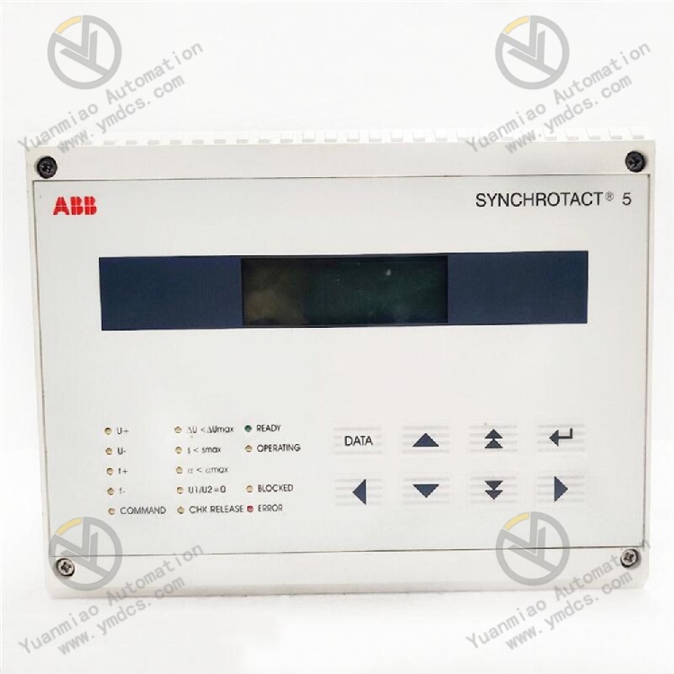
Model: SYN5201‑2277 3BHB006714R0277
Brand: ABB
Product Name: Digital Automatic Synchronizing Device, Intelligent Generator Synchronization Controller
Product Positioning
ABB SYN5201‑2277 3BHB006714R0277 belongs to the high-end intelligent digital synchronizer of ABB SYNCHROTACT 5 series. It is a dedicated core control equipment for accurate automatic synchronization of generator sets, standby power supplies and station service power systems. Designed for power industry scenarios including thermal power, hydropower, gas power generation, biomass power generation and industrial captive power plants, it can accurately detect and automatically regulate voltage, frequency and phase difference between generators and power grids to achieve bumpless and disturbance-free synchronization. It serves as a key original core equipment and regular maintenance spare part to guarantee safe grid connection, stable switching of generator sets and eliminate faults caused by synchronization impact.
Core Functions
Integrated with high-precision synchronization detection and intelligent regulation algorithms, the device collects real-time voltage, frequency and phase parameters on the generator side and system side, automatically calculates synchronization deviation values, outputs precise speed and voltage regulation commands, and rapidly tracks power grid parameters. Once synchronization conditions are met, it automatically sends closing commands. It features accurate synchronization interlock, abnormal condition interception, fault self-diagnosis logging and full-process monitoring during synchronization. It can fundamentally prevent high-risk accidents such as out-of-phase synchronization, wrong-phase closing and synchronization with excessive voltage/frequency difference, and effectively avoid risks including unit impact, power grid oscillation and equipment damage. It supports multiple operation modes: fully automatic, semi-automatic and manual-assisted synchronization, adapting to full-range working conditions such as no-load grid connection of units, standby power switching and dual-power paralleling, ensuring stable, safe and efficient operation of power systems.
Applicable Systems
It is widely compatible with supporting control systems of various synchronous generator sets, power plant DCS systems, PLC automatic control systems and station service dual-power switching systems, and perfectly matches the full range of ABB power control platforms and mainstream third-party power automation systems. Its communication specifications, wiring logic and control contacts fully comply with power industry standards. Suitable for renovation of new and old power plant units, replacement of legacy synchronizers, upgrading of automatic synchronization systems and expansion of dual-power linkage. Direct in-situ replacement requires no major modification of wiring and control logic, delivering outstanding compatibility, versatility and interchangeability.
Application Scenarios
Mainly applied in thermal power plants, hydropower plants, gas turbine power plants, biomass power plants, distributed energy stations, industrial and mining captive power plants, and substation standby power supply systems. It is used for automatic synchronization of single/multiple generator sets, seamless switching of station dual power supply, grid connection of islanded units and paralleling of power grid tie lines. It fully meets the stringent continuous, safe and high-precision operating requirements of the power industry, and adapts to unattended automatic synchronization operation and maintenance demands of smart power plants.
2. Technical Features
High-precision Synchronization Detection for Bumpless Stable Grid Connection Equipped with industrial-grade high-precision sampling and computing chips, the device realizes millisecond-level parameter acquisition and deviation calculation. It strictly controls synchronization thresholds: phase difference ≤±1°, frequency difference ≤±0.1Hz, voltage difference ≤±5%, exceeding the precision standard of conventional synchronizers. It dynamically tracks real-time parameter changes of power grids and generator sets, automatically fine-tunes unit speed and terminal voltage to precisely match grid conditions. Zero current impact, power oscillation and voltage disturbance occur at the moment of synchronization, maximizing protection of generators, transformers and grid equipment, and greatly improving synchronization success rate and system stability.
Multi-mode Intelligent Synchronization Adaptable to Full-range Operating Conditions Three switchable operation modes are available: fully automatic synchronization, semi-automatic synchronization and manual-assisted synchronization, which can be freely selected according to unit operating status, maintenance requirements and grid dispatching conditions. In fully automatic mode, the whole process including parameter detection, deviation regulation, closing judgment and command output is completed without manual intervention. Semi-automatic mode supports manual parameter calibration. Manual mode provides accurate data reference to avoid human operation errors. It adapts to various complex working conditions including initial unit synchronization, routine start-stop grid connection, post-fault restart synchronization and dual-power switching with strong scenario adaptability.
Comprehensive Anti-mis-synchronization Interlock with High Safety Protection Level Embedded with multiple safety interlock and fault protection logic, it provides multi-layer protection mechanisms including out-of-synchronization interlock, over-limit voltage difference interlock, over-limit frequency difference interlock, abnormal phase interlock, loss-of-voltage interlock and device fault interlock. Operating parameters are monitored throughout synchronization. Closing commands will be locked and alarms triggered immediately once any parameter exceeds safe thresholds, fundamentally preventing major power safety accidents such as out-of-phase closing, wrong-phase synchronization and synchronization under faulty conditions. With forced contact monitoring function, it continuously monitors the status of closing relay contacts to eliminate mis-synchronization risks caused by contact adhesion and false operation, comprehensively securing synchronization operations.
Multi-protocol Communication Compatibility for High Intelligent Integration Standard Ethernet interface is equipped. It supports local commissioning via SynView upper computer debugging tool and natively adopts IEC 61850 power-dedicated communication protocol. Dual IP address segmented configuration is available to satisfy equipment configuration & maintenance and real-time communication demands of power systems respectively. It can seamlessly connect with power plant DCS, power monitoring background and remote operation & maintenance platforms, supporting real-time upload of synchronization data, remote tuning of operating parameters, remote reading of fault logs and online firmware upgrade, fitting the automation, unattended and remote operation & maintenance architecture of smart power plants.
Full-process Self-diagnosis and Event Tracing for Efficient Maintenance Built with dual-channel event recording system, including time-stamped fault event logs and internal diagnosis logs. It records full-process synchronization data, parameter violation records, fault alarms, equipment operating status and operation history. Equipped with LCD display, it enables on-site real-time viewing of synchronization parameters, equipment status and fault codes to accurately locate fault points and abnormal causes. Data can be exported for review on upper systems, significantly shortening troubleshooting, condition analysis and equipment maintenance cycles and reducing unit outage losses.
Industrial-grade Anti-interference and Durable Design Adaptable to Harsh Power Conditions The whole unit adopts industrial-grade components and standardized rack structure, and has passed rigorous tests on high/low temperature resistance, vibration resistance, dust resistance, moisture resistance and electromagnetic compatibility. It adapts to complex power plant environments featuring severe electromagnetic interference, voltage fluctuation, frequent temperature variation and equipment vibration. Integrated circuits for electrical isolation, surge suppression, electromagnetic shielding and power filtering ensure no parameter drift, logic disorder or program crash during long-term continuous operation. It delivers superior stability and reliability to meet 24/7 uninterrupted operation requirements of power equipment.
- Standardized Modular Design for Convenient Installation and Replacement It adopts standard rack mounting structure combining rear screw terminals and spring terminals, featuring standardized wiring, reliable connection and easy assembly & disassembly. Equipment dimensions, pin definitions, contact logic and communication protocols fully comply with ABB original specifications and power industry standards. Direct in-situ replacement of faulty legacy synchronizers is supported without new hole drilling, rewiring or major modification of control logic, covering routine maintenance, fault replacement, system upgrading and legacy unit renovation scenarios.
3. Specification Parameters
| Item | Parameter |
|---|---|
| Model | SYN5201‑2277 3BHB006714R0277 |
| Manufacturer | ABB |
| Equipment Type | Intelligent Digital Automatic Synchronizing Device, Generator Synchronization Controller |
| Application Scope | Automatic synchronization of various synchronous generator sets, power plant dual-power switching, paralleling of grid tie lines, renovation and upgrading of legacy synchronization systems |
| Core Functions | High-precision voltage/frequency/phase detection, automatic speed & voltage regulation, intelligent synchronization closing, multi-layer synchronization interlock, fault self-diagnosis, event logging, multi-protocol communication, remote parameter tuning and upgrade |
| Synchronization Control Precision | Phase difference ≤±1°; Frequency difference ≤±0.1Hz; Voltage difference ≤±5% |
| Operation Modes | Switchable between fully automatic, semi-automatic and manual-assisted modes |
| Communication Protocols | IEC 61850, Ethernet communication, compatible with SynView upper computer debugging tool |
| Communication Distance | Max. 100m for Ethernet |
| Input Power Supply | AC/DC 85~265V wide-range power supply |
| Sampling Voltage Range | Compliant with standard 0~120V synchronization sampling voltage for conventional power plants |
| Output Contact Specification | Passive relay contact output, compatible with closing, speed regulation, voltage regulation and alarm signal circuits |
| Safety Interlock Mechanism | Multi-layer protection against voltage difference, frequency difference, phase abnormality, loss of voltage, contact failure and equipment anomaly |
| Operating Temperature | -25℃~+60℃ (standard operating condition for power equipment) |
| Storage Temperature | -40℃~+85℃ |
| Ambient Humidity | 5%~95%RH, non-condensing, suitable for indoor power plant cabinet environment |
| Protection Performance | Electromagnetic shielding, surge suppression, electrical isolation, vibration & dust resistance, moisture & corrosion resistance, certified by EMC standards for power industry |
| Operation Mode | Real-time parameter sampling, automatic deviation regulation, intelligent closing judgment, full-condition monitoring, automatic fault interlock & alarm, real-time data upload |
| Commissioning & Upgrade Method | Local commissioning via SynView tool, remote online parameter tuning and firmware upgrade |
| Installation Method | Standard cabinet rack mounting, rear screw + spring terminal wiring, modular assembly and replacement |
| Equipment Characteristics | High-precision synchronization, multi-layer safety interlock to prevent false operation, flexible multi-mode adaptation, intelligent tracing for maintenance, stable operation with strong anti-interference, plug-and-play interchangeability, suitable for long-term safe grid connection of generator sets |
4. Working Principle
4.1 Power-on Initialization and Overall Self-diagnosis
After power supply is switched on, the device automatically completes power-on initialization and full-dimensional hardware self-inspection. It sequentially verifies the integrity of sampling circuits, computing chips, communication ports, relay output contacts and storage units, and simultaneously checks the validity of device firmware, parameter configuration and circuit wiring. It comprehensively identifies potential hidden troubles including hardware faults, program disorder, parameter anomalies, loose wiring and contact failure. If self-test passes, the device enters standby monitoring state, waits for synchronization start commands in real time and establishes communication connection with upper systems and unit control loops.
4.2 Real-time Dual-side Parameter Sampling and Deviation Calculation & Analysis
During standby or synchronization operation, the device continuously collects three core parameters at high speed: voltage amplitude, operating frequency and phase angle on the generator side and grid side. Built-in high-precision computing algorithms conduct real-time data filtering, calibration and deviation calculation to accurately obtain voltage difference, frequency difference and phase difference between two sides. It dynamically compares preset safe synchronization thresholds, tracks parameter variation trends and predicts synchronization conditions, providing accurate data support for subsequent speed/voltage regulation and closing judgment, and eliminating interference from invalid and distorted data throughout the process.
4.3 Automatic Speed & Voltage Regulation and Parameter Tracking Matching
When deviations between unit and grid parameters are detected, the device intelligently outputs precise speed and voltage regulation commands to the unit governor system and excitation system according to deviation magnitude and variation rate. It dynamically adjusts unit rotation speed to correct frequency deviation and fine-tunes excitation current to eliminate voltage deviation, continuously narrowing frequency and voltage differences to realize synchronous matching of parameters on both sides. Regulation proceeds smoothly without overshoot or oscillation, rapidly approaching the optimal synchronization condition.
4.4 Intelligent Closing Judgment and Bumpless Synchronization
When voltage difference, frequency difference and phase difference between the generator set and power grid all meet preset high-precision synchronization thresholds, with no device alarms and normal circuit status, the device accurately predicts the phase coincidence moment, sends pre-closing commands in advance and triggers closing relays at the optimal synchronization point to complete circuit breaker closing. Extremely high parameter matching is achieved at the moment of synchronization with no current impact or power fluctuation, realizing stable, safe and rapid grid connection of generator sets.
4.5 Full-process Condition Monitoring and Multi-layer Safety Interlock Protection
Throughout synchronization and unit grid-connected operation, the device continuously monitors dual-side electrical parameters, equipment operating status, relay contact conditions and communication links. Once anomalies such as excessive voltage difference, excessive frequency difference, phase disorder, loss of voltage, contact adhesion, equipment failure or communication interruption occur, the interlock mechanism is activated immediately to lock closing commands and avoid risks of false synchronization and faulty synchronization. Local alarms are triggered and fault information is uploaded to upper monitoring systems, with fault sequence and parameters recorded to achieve traceable, investigable and preventable faults.
4.6 Data Interaction and Remote Intelligent Operation & Maintenance
Based on IEC 61850 Ethernet communication architecture, the device uploads full-process synchronization data, electrical parameters, operating status, fault logs and operation records to DCS and power monitoring platforms in real time. Meanwhile, it receives commands from upper computers for remote parameter tuning, mode switching and program upgrading to realize parameter update and function iteration. Equipped with dual-channel event storage, it completely retains equipment operation and synchronization data, supporting on-site inquiry and background export for review, and enabling intelligent, remote and unattended full-lifecycle operation & maintenance of synchronization systems.
5. Common Problems and Solutions
5.1 Phenomenon: No display after power-on, device fails to start and no response
Possible Causes
① Abnormal power supply voltage out of AC/DC 85~265V range, loose wiring and poor contact;
② Fault in internal power circuit, blown internal fuse;
③ Damaged firmware, program crash and startup failure;
④ Aging hardware, damaged main control chip or power supply unit;
⑤ Poor grounding resulting in abnormal initialization.
Solutions
Cut off device power supply, measure input voltage and circuit continuity, fasten terminals and eliminate hidden risks of abnormal voltage and loose connections. Inspect internal fuses and replace blown ones. Reset device program, re-flash compatible original firmware and restore factory default parameters. Standardize equipment grounding wiring to resolve grounding anomalies. If startup still fails after confirming normal power supply, wiring, program and grounding, hardware damage is confirmed and original SYN5201‑2277 device replacement is required.
5.2 Phenomenon: Automatic synchronization unavailable, no closing command output despite matched parameters
Possible Causes
① Overly strict synchronization interlock parameters and disordered threshold settings;
② Damaged or adhered closing relay contacts or faulty circuit wiring;
③ Disconnected external closing circuit and unsatisfied interlock conditions;
④ Contact monitoring function of the device triggering interlock protection;
⑤ Abnormal program operation and stuck closing logic.
Solutions
Log in to the background or local interface, recalibrate voltage difference, frequency difference and phase thresholds for synchronization and restore original standard parameters. Measure continuity of closing relay contacts, troubleshoot adhesion and damage, and fasten wiring of closing circuits. Verify external unit interlocks and circuit breaker preconditions to ensure all prerequisites for synchronization are fulfilled. Reset contact monitoring protection logic of the device to release false interlocks. Reboot the device and refresh synchronization control logic. If no closing command is generated after rectification, faults exist in the control circuit or hardware and device replacement is needed.
5.3 Phenomenon: Large synchronization parameter deviation, insufficient regulation precision, impact and oscillation during synchronization
Possible Causes
① Improper tuning of speed and voltage regulation parameters; regulation rate mismatches unit characteristics;
② Loose wiring of dual-side sampling circuits and signal interference leading to distorted sampling data;
③ Deviated synchronization thresholds and excessively low precision setting;
④ Response lag of unit governor and excitation systems;
⑤ Degraded precision and abnormal operation of the device sampling unit.
Solutions
Retune speed and voltage regulation PID parameters according to rated unit conditions to match unit response speed. Fully inspect sampling wiring on generator and grid sides, fasten terminals, optimize shielding grounding and isolate electromagnetic interference to guarantee accurate sampling data. Calibrate synchronization precision thresholds and restore original high-precision configuration. Cooperatively verify response performance of unit governor and excitation systems to eliminate response lag. If impact still occurs during synchronization after circuit and parameter rectification, faults exist in the sampling and computing unit and device replacement is required.
5.4 Phenomenon: Frequent false interlock, unauthorized synchronization prohibition and abnormal alarm parameters
Possible Causes
① Unreasonable interlock protection thresholds and excessively small filtering parameters;
② Transient parameter fluctuation caused by on-site electromagnetic interference leading to misjudgment of over-limit;
③ Aging sampling cables and poor contact resulting in instantaneous signal anomalies;
④ False triggering of device self-diagnosis logic and abnormal program cache;
⑤ Hardware performance drift inside the equipment.
Solutions
Recalibrate synchronization interlock thresholds and data filtering parameters to adapt to on-site conditions and increase tolerance for transient fluctuations. Optimize shielding grounding of sampling circuits to enhance anti-interference capability and filter transient interference signals. Inspect sampling cables section by section, replace aged wires and fasten terminals to eliminate poor contact risks. Clear operation cache, restart the device to reset protection logic and upgrade stable firmware. If false interlock persists, hardware parameter drift is confirmed and original device replacement is required.
5.5 Phenomenon: Communication disconnection, no data uploaded to background, failure of remote tuning and commissioning
Possible Causes
① Damaged Ethernet cables, loose ports and unstable links;
② Incorrect IEC 61850 communication parameters and IP address configuration, disconnected network segments;
③ Mismatched version of upper debugging tool and disabled communication access rights;
④ Stuck communication program of the device and faulty communication unit;
⑤ Protocol incompatibility of background systems.
Solutions
Inspect Ethernet cables and ports, replace damaged wires and fasten connectors to stabilize links. Verify and unify device IP address, communication protocol and port parameters to match background network configuration. Adopt compatible SynView debugging tool version and enable remote tuning and data upload permissions. Restart communication program and reset communication services. If local communication test still fails, hardware damage of the communication unit is confirmed and device replacement is required.
5.6 Phenomenon: Excessive heat generation after long-term operation, parameter drift and occasional disorder of synchronization logic
Possible Causes
① Severe dust accumulation in control cabinet, blocked air duct leading to poor heat dissipation and high temperature;
② Frequent synchronization operations resulting in redundant program accumulation;
③ Power supply voltage fluctuation and ripple interference impairing equipment stability;
④ Logic stagnation and performance degradation of firmware after long-term continuous operation;
⑤ Component aging inside the device triggering parameter drift.
Solutions
Shut down equipment, clean dust in the cabinet and on the device surface, optimize ventilation and heat dissipation to stabilize operating temperature. Inspect power quality, stabilize voltage and filter ripple and clutter interference. Upgrade optimized original firmware, clear redundant programs and improve computing stability. Reasonably control synchronization frequency to avoid long-term overload operation. Repeated parameter drift and logic disorder indicate hardware aging. Spare parts replacement shall be arranged in advance to guarantee safe unit synchronization.