Description
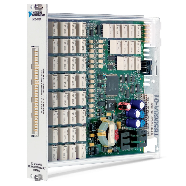
NI SCXI-1127
1. Basic Information
NI SCXI-1127 (Part Number: 776572-27) is a high-voltage electromechanical relay matrix/multiplexer module. Positioned as a high-density and high-withstand-voltage signal switching component, it is specially designed for industrial testing and data acquisition systems. It is responsible for routing and switching multi-channel signals, serving as core equipment for centralized large-scale signal collection and distribution within the SCXI architecture.
It acts as a signal hub in test systems, configurable flexibly as either a multiplexer or matrix switch. It routes signals from multiple Devices Under Test (DUT) to measuring instruments such as multimeters and oscilloscopes as required, and distributes excitation signals to different test points. It enables efficient test architectures of single-instrument multi-measuring-point and multi-instrument single-measuring-point, greatly cutting down hardware costs and wiring complexity of test systems.
2. Technical Specifications
2.1 Core Electrical & Switching Specifications
- Channel Configuration: 64 channels with software-configurable topologies: 1×32 2-wire multiplexer, 2×16 2-wire multiplexer, 4×8 2-wire multiplexer; expandable to 4×8 2-wire matrix with SCXI-1332 terminal block.
- Withstand Voltage & Load: High voltage mode: 250 Vrms (200 mA load), 30 VDC (1 A load); Low voltage mode: low thermal offset relays for precision voltage and current measurement.
- Switching Performance: Bandwidth 11 MHz; relay on-resistance <1 Ω; isolation voltage 500 Vrms (channel to channel / channel to ground); switch service life ≥10⁶ cycles under rated load.
- Scan Mode: Supports hardware timed synchronous scan and handshake scan; only continuous scan is available, single-shot trigger scan is not supported.
Driver Software: NI-SWITCH driver, compatible with LabVIEW, Measurement Studio, C/C++ and other development environments; configurable via MAX (Measurement & Automation Explorer).
2.2 Physical & Structural Specifications
- Mounting Method: Standard slot installation for SCXI chassis, compatible with SCXI-1000/1001/1100 and other chassis, supporting multi-module stacking and expansion.
- Dimensions: 30.5 mm × 172.7 mm × 198.1 mm (H × W × D)
- Weight: Approximately 680 g (1 lb 8 oz)
- Interface & Enclosure: Industrial-grade metal shielded housing; SCXI bus interface at the rear and terminal block interface at the front; EMC-compliant electromagnetic shielding design, required to use with shielded cables.
Environmental Adaptability: Operating temperature: 0℃~55℃; Storage temperature: -40℃~70℃; Operating humidity: 10%~90% non-condensing.
2.3 Core Functions & Compatibility Specifications
- Core Functions: Multi-channel high/low voltage signal switching, matrix signal routing, excitation signal distribution, automatic scanning testing, channel isolation protection.
- Integrated Features: Low conduction loss of electromechanical relays for precision measurement; high inter-channel isolation to suppress signal crosstalk; hardware timed scanning ensures synchronous acquisition accuracy of multi-channel data.
- Compatibility: Matches full series of NI SCXI chassis and terminal blocks; compatible with PXI/PCI bus measuring instruments e.g. NI 4070 multimeter; supports legacy NI-DAQ and NI-DAQmx drivers.
- Reliability & Practicability: Industrial reinforced design with vibration and electromagnetic interference resistance; relay status indicator lights facilitate on-site troubleshooting; modular design supports hot-swap (chassis dependent) for easy maintenance.
3. Working Principle
After being inserted into the SCXI chassis and powered on, the module completes self-test and initialization via NI-SWITCH driver to inspect the status of relay arrays and bus interfaces. Engineers configure channel topology (multiplexer/matrix), withstand voltage threshold and scanning rate in software to finish matching between the module and test systems.
Control commands are sent to the module through SCXI bus to drive corresponding relays to close or open, establishing connections between input channels and output ports. In multiplexer mode, a single common terminal polls multiple input channels; in matrix mode, cross closing of row and column relays realizes signal routing between any channels.
When triggered by hardware timing, the module switches channels in preset sequence and routes measured signals including voltage, current and resistance to measuring instruments. Synchronous scan mode enables simultaneous action of all relays with one single signal; handshake scan mode realizes two-way signal interaction between instruments and modules to guarantee data synchronization. Collected data is uploaded to upper computers for processing via SCXI bus.
500 Vrms isolation between channels prevents high-voltage signals from intruding into low-voltage measurement loops. Relays maintain high impedance when open to avoid electric leakage. Overvoltage and overcurrent protection thresholds can be set in software to cut off channels automatically under abnormal conditions and protect the module and rear-end instruments.
4. Application Scenarios
4.1 Power Electronic Testing
Ideal for testing high-voltage equipment such as power supplies, inverters and transformers. It switches voltage and current signals of different windings and power devices to complete multi-point tests on insulation, withstand voltage and on-resistance.
4.2 Automotive Electronic Testing
Applied to multi-channel testing of vehicle high-voltage batteries, motor controllers and wiring harnesses. It switches signals of high-voltage loops and low-voltage control loops to support batch detection of insulation resistance, high-voltage breakdown and conduction performance.
4.3 Aerospace Testing
Used for high and low voltage signal switching of aviation cables, sensors and power modules. It performs multi-channel precision scanning tests in harsh electromagnetic environments to ensure test stability and reliability.
4.4 Industrial Automation & Data Acquisition
4.5 Precision Instrument Calibration