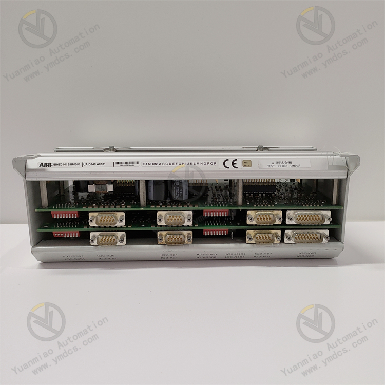
Description
1. Product Overview
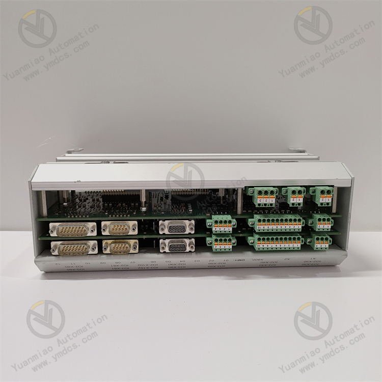
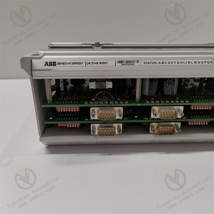
Model: UAD149A0001
Part Number: 3BHE014135R0001
Brand: ABB
Product Name: Generator Excitation Control Unit / High-Precision Excitation Regulator Module
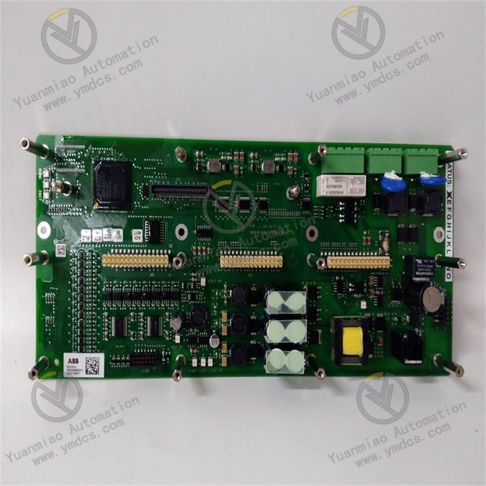
Product Positioning The UAD149A0001 is a core excitation control module dedicated to the ABB System 800xA / AC800PEC power control system, serving as a critical regulation unit for excitation systems of large synchronous generator sets. As the core hardware for excitation regulation in power plants, it precisely controls generator excitation current, regulates unit reactive power and stabilizes terminal voltage. It is widely applied in complete excitation control systems for large generator units in thermal power, hydropower and cogeneration plants, and acts as a key industrial spare part to guarantee stable grid interconnection and steady-state unit operation.
Core Functions It collects real-time operating parameters including generator terminal voltage, stator current, reactive power and power factor, and dynamically outputs controllable DC excitation current via built-in high-precision regulation algorithms. It accurately adapts to full operating conditions such as unit grid connection, steady-state operation, load variation and fault disturbance, automatically stabilizing generator terminal voltage, balancing system reactive power distribution and suppressing grid power fluctuation. Equipped with linkage protection capabilities against overexcitation, underexcitation, overcurrent and other abnormalities, it effectively avoids faults such as generator loss of excitation, oscillation and voltage overlimit, ensuring safe and stable operation of generator sets and power systems.
Applicable Systems ABB System 800xA power automation system, AC800PEC, AC800M controllers and complete ABB generator excitation control systems. Compatible with DCS of large power plants and coordinated control architectures for power grid dispatching.
Application Scenarios Extensively deployed in thermal power plants, hydropower plants, biomass power stations, cogeneration plants and other industrial power facilities. It is installed exclusively in generator excitation control cabinets and main system cabinets, supporting full operating modes of large synchronous generators including grid-connected generation, island operation, peak regulation and frequency modulation. It is a core maintenance spare part for excitation systems of power generating units.
2. Technical Features
High-Precision Closed-Loop Excitation Regulation Adopts proprietary ABB excitation regulation algorithms and supports multi-mode closed-loop regulation: voltage closed loop, reactive power closed loop and power factor closed loop. It features fast dynamic response and high regulation accuracy, precisely correcting unit voltage deviation and reactive power offset, effectively restraining operating drift caused by unit load fluctuation and grid disturbance, and maintaining constant and controllable generator output parameters.
Adaptive Performance for Multiple Operating Conditions Automatically switches regulation logic to adapt to different scenarios including unit startup/shutdown, grid connection/disconnection, peak regulation and fault recovery. It can precisely cope with complex operating states such as no-load, loaded, overload and disturbance impact, balancing startup stability and flexibility of load regulation to meet the demand of continuous all-day operation in power plants.
Comprehensive Safety Protection Mechanism for Generators Built-in multiple hardware and software protection logics including overexcitation limit, underexcitation limit, excitation overcurrent, voltage overlimit and loss-of-excitation monitoring. It monitors abnormal conditions in excitation circuits in real time. Upon fault detection, it automatically executes amplitude limiting, de-excitation, output blocking and alarm triggering to prevent unit oscillation, out-of-step and equipment burnout induced by abnormal excitation, complying with high safety redundancy standards of the power industry.
Industrial-Grade Anti-Interference and High Stability Designed with power-specialized EMC electromagnetic compatibility, integrated with power filtering, surge suppression and signal isolation circuits to resist strong electromagnetic interference generated by high-voltage equipment, frequency converters and switchgears in power plants. Military-grade PCBs and surface-mount components deliver outstanding shock resistance, dust resistance, temperature variation tolerance and anti-aging performance, supporting 7×24-hour non-stop long-term operation in power stations.
Full Compatibility with Original Manufacturer Systems Custom-developed for ABB power excitation control systems. Hardware pinouts, bus communication protocols, regulation logic and parameter architecture fully match original systems without compatibility deviation. No extra program adaptation or hardware modification is required; direct in-situ replacement of original modules is supported for retrofitting of aged units and new unit matching.
Modular Design for Convenient and Efficient Maintenance Standard plug-in structure for cabinet mounting with easy insertion and removal and reliable fixation. Independent disassembly and replacement are available without altering wiring and control logic of the whole excitation system. Onboard status indicators visually display module operation, fault and communication status, greatly shortening downtime and maintenance costs for troubleshooting and spare part replacement
- Configurable Parameters with Strong Adaptability Supports parameter configuration and calibration via upper software. Core parameters such as power factor, current thresholds and regulation gain can be customized according to unit capacity, transformer ratio and process requirements, meeting excitation regulation demands of synchronous generators of various specifications with high flexibility for different scenarios.
3. Specification Parameters
| Item | Parameter |
|---|---|
| Model | UAD149A0001 |
| Part Number | 3BHE014135R0001 |
| Device Type | Generator Excitation Control & Regulation Module |
| Applicable Systems | ABB System 800xA, AC800PEC, AC800M Power Control Systems |
| Control Modes | Terminal voltage closed loop, reactive power closed loop, power factor closed loop regulation |
| Core Functions | Excitation current regulation, generator voltage stabilization, reactive power control, fault protection, operating condition self-diagnosis |
| Power Supply | Stabilized power supply via system backplane bus |
| Mounting Method | Standard plug-in cabinet mounting, DIN rail mounting |
| Operating Temperature | 0℃~65℃ (rated cabinet operating condition) |
| Storage Temperature | -20℃~85℃ |
| Ambient Humidity | 5%~95%, non-condensing |
| Protection Design | Optoelectronic isolation, surge suppression, EMC compliance, signal filtering protection |
| Applicable Equipment | Medium & large synchronous generators, steam turbine generator sets, hydro turbine generator sets |
| Weight | Approx. 1.68 kg |
| Origin | Original imported from Switzerland |
| Product Characteristics | High-precision excitation regulation, multi-mode closed-loop control, multiple fault protection, anti-interference, exclusive system compatibility, configurable parameters |
4. Working Principle
System Initialization and Parameter Self-Check After power-on, the module automatically completes hardware self-test, bus communication matching, core parameter loading and logic initialization. It verifies preset excitation parameters, protection thresholds and regulation gains defined by the system. Once hardware circuits, communication links and parameter configuration are confirmed normal, it enters standby regulation mode to lay a foundation for precise excitation control of the generator unit.
Collection and Analysis of Generator Operating Parameters Key operating data including generator terminal voltage, stator current, rotor excitation current, reactive power, active power and power factor are collected in real time via system signal loops. The acquired signals are preprocessed by filtering, isolation and noise reduction to eliminate electromagnetic interference noise on site and restore accurate raw operating data of the generator.
Closed-Loop Calculation and Excitation Command Output Based on built-in core regulation algorithms, the module continuously compares actual operating parameters with rated system thresholds and dynamically calculates excitation regulation deviation. It automatically outputs precise excitation control commands according to the unit operating mode to adjust DC current output from the excitation power unit, modifying generator excitation status in real time, stabilizing terminal voltage and system reactive power balance and realizing precise closed-loop regulation.
Adaptive Logic Switching for Full Operating Conditions Variations of unit operating conditions are monitored continuously. Optimal regulation logic is switched automatically under scenarios including unit startup/shutdown, grid connection, load variation and grid disturbance: precise voltage stabilization during no-load operation, smooth reactive power matching after grid connection, and rapid compensation during load fluctuation, avoiding generator voltage oscillation and reactive power imbalance and ensuring stable unit operation
- Fault Monitoring and Safety Protection Linkage During operation, fault conditions such as excitation overcurrent, underexcitation, overexcitation, voltage overlimit and abnormal signals are monitored in real time. Once an abnormality is detected, protection actions including excitation limiting, current reduction and output blocking are executed immediately. Fault codes and alarm information are uploaded to the main control system simultaneously to trigger corresponding interlock protection, mitigating risks of unit instability and equipment damage and safeguarding safe operation of the excitation system and generator set.
5. Common Faults and Troubleshooting
Phenomenon: No response after power-on, no running indicator light, hardware unrecognized by the system Possible Causes
① Abnormal backplane bus power supply of cabinet, poor contact of slot;
② Oxidation and dust accumulation on module gold fingers, failed contact of communication pins;
③ Damage to internal power circuit of module, loss of firmware program.
Troubleshooting Cut off system power and fully discharge; extract the module, clean dust and impurities on gold fingers and backplane slots, then reinsert and fix steadily. Measure backplane bus voltage and communication status to troubleshoot slot faults. Restart the system for hardware re-detection and re-flash matching firmware. If no response remains with normal power supply and communication, hardware failure of the module is confirmed and original spare part replacement is required.
Phenomenon: Severe fluctuation of generator terminal voltage, unstable excitation regulation Possible Causes
① Drift of module regulation parameters, unreasonable gain setting;
② Interference on signal acquisition cables leading to distorted signal transmission;
③ Aging of module signal conditioning circuit, declined regulation accuracy;
④ Frequent abrupt change of unit load.
Troubleshooting Inspect signal acquisition wiring, implement shielding and grounding to eliminate electromagnetic interference. Access the system background to recalibrate excitation regulation gain, voltage stabilization threshold and reactive power parameters and optimize regulation logic. Stabilize unit load conditions. If abnormal fluctuation persists after parameter calibration, the module suffers degraded hardware precision and needs replacement.
Phenomenon: Frequent overexcitation/underexcitation protection alarms, abnormal unit reactive power Possible Causes
① Offset protection threshold parameters, unreasonable parameter matching;
② Abnormal excitation current sampling signal with data deviation;
③ Disturbed module protection logic and abnormal program;
④ Impact from grid voltage disturbance.
Troubleshooting Verify and correct overexcitation, underexcitation and current protection thresholds to match rated unit operating conditions. Calibrate sampling circuit accuracy and eliminate signal distortion issues. Restart the module to reset program and restore factory default configuration. Mitigate grid disturbance impact. If alarms continue, module failure is confirmed and spare part replacement is required.
Phenomenon: Module communication interruption, abnormal data exchange with main control system Possible Causes
① Poor contact of backplane bus, loose communication cables;
② Mismatched module communication protocol, disordered address parameters;
③ Aging of module communication chip, faulty bus circuit.
Troubleshooting Re-plug and fasten module and backplane bus connectors, clean communication pins. Verify module communication address, baud rate and protocol parameters to unify settings with the system. Troubleshoot bus network interference and optimize shielding grounding. If disconnection persists with correct communication parameters, communication hardware failure of the module is confirmed and replacement is needed.
Phenomenon: Unbalanced reactive power distribution after unit grid connection, failed power factor regulation Possible Causes
① Incorrect settings of power factor and reactive closed-loop parameters;
② Failure of module closed-loop regulation logic;
③ Sampling transformer signal deviation causing misjudgment during regulation.
Troubleshooting Recheck transformer ratio, power factor setpoint and reactive power regulation range parameters. Calibrate sampling signal accuracy and correct data deviation. Restart the module to activate closed-loop regulation logic. If regulation remains ineffective after parameter verification, functional failure of the module is confirmed and original module replacement is required.
Phenomenon: Excessively high operating temperature of module, abnormal local heating inside cabinet Possible Causes
① Blocked air duct of control cabinet with heavy dust accumulation leading to poor heat dissipation;
② Long-term high-load operation resulting in component aging and abnormal power consumption inside module;
③ Abnormally high bus supply voltage.
Troubleshooting Clean cabinet cooling vents and air ducts to improve ventilation and heat dissipation and maintain cabinet temperature within rated range. Measure bus supply voltage and rectify abnormal power supply. Continuous overheating indicates component aging of the module; replace spare parts in advance to avoid unplanned shutdown faults.