
Description
1. Product Overview
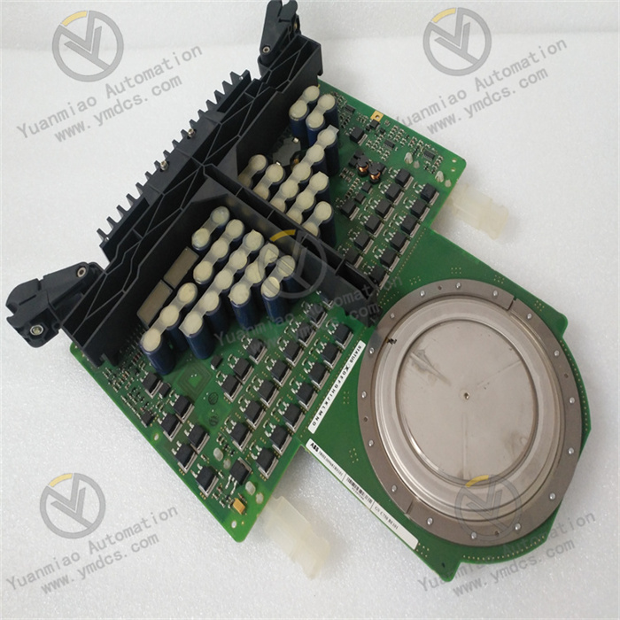
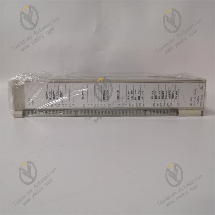
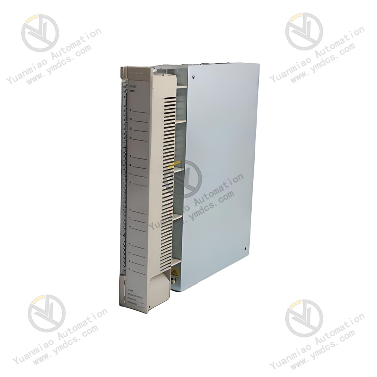
Full Model: LDMUI-01
Manufacturer: ABB
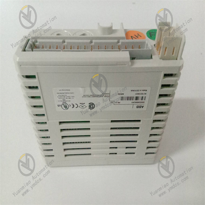
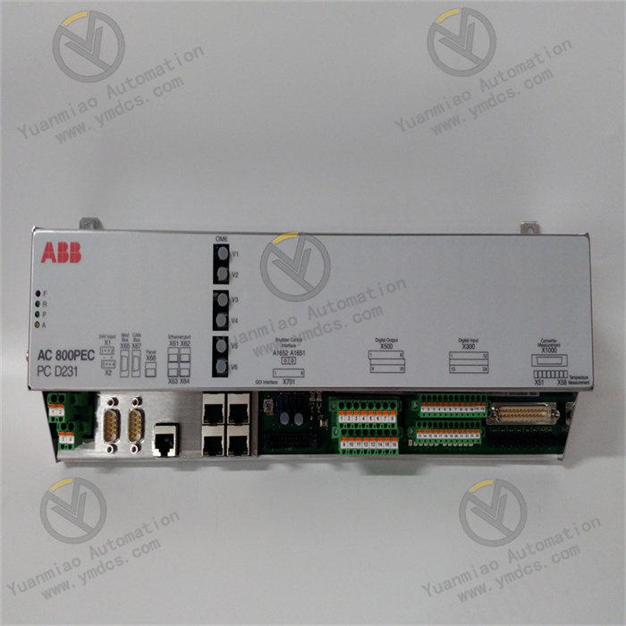
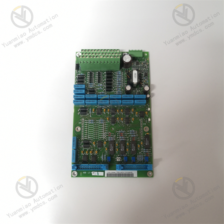
Product Name: 16-Channel Isolated High-Power Digital Output Module, Dedicated DO Module for AC800M DCS System
Product Positioning
ABB LDMUI-01 is a high-performance high-power digital output module matched with ABB AC800M and AC800PEC power and process DCS systems. It serves as a core I/O card for process control and SIS safety systems in power plants, chemical industry, metallurgy and other sectors. Designed for driving high-power loads on industrial sites, the module integrates 16 independent isolated output channels. It features core capabilities including direct high-current driving, channel-independent protection, fault self-diagnosis and hot-swap maintenance. It can drive field actuators without external intermediate relays, effectively simplifying control cabinet loop structures and reducing system fault points. It is a critical logic output and interlock control unit in industrial automatic control systems.
Core Function
This module is mainly responsible for outputting logic control commands of the DCS system. It stably transmits switching control signals to directly drive 24 V DC industrial solenoid valves, valve actuators, contactor coils, audible and visual alarms, auxiliary equipment start/stop loops, ESD emergency trip loops and other high-power loads. Equipped with comprehensive channel-level fault detection and electrical protection functions, it can monitor abnormal conditions such as circuit open circuit, short circuit, overload and reverse power supply polarity in real time, and quickly isolate faulty channels. It prevents fault propagation, module burnout and equipment misoperation, greatly improving the stability and safety of industrial interlock control and safety protection loops, and ensures long-term continuous and reliable operation of generating units and process equipment.
Applicable Systems
Exclusively compatible with the full series of ABB AC800M and AC800PEC power control systems and process DCS systems, and fully compatible with ABB 800xA monitoring platform and Control Builder M configuration software. Matched with the original standard I/O rack backplane bus, it can seamlessly network and interact with system main control CPU, analog modules, digital input modules and other various I/O cards. It supports in-situ hot-swap replacement of legacy digital output modules of the same specification without modifying system control logic, rewiring or complicated configuration commissioning. Featuring outstanding compatibility and interchangeability, it fits scenarios including new and existing system renovation, daily maintenance and emergency fault replacement.
Application Scenarios
Widely deployed in DCS process control systems and SIS safety instrumented systems across thermal power generation, hydropower generation, new energy wind power, petrochemical industry, metallurgy and heavy industry. Typical applications include start/stop control of boiler auxiliary equipment, driving of process on-off valves, unit interlock protection trip, ESD emergency shutdown control, on-site audible and visual alarm output, logic interlock of conveying equipment, driving of industrial contactors, and safety interlock for high-risk processes. It adapts to harsh industrial operating conditions characterized by high loads, strong electromagnetic interference, high safety requirements and 24-hour uninterrupted operation.
2. Technical Features
Highly Integrated Multi-Channel Design with Direct High-Power DrivingA single module integrates 16 independent digital output channels. The maximum output current reaches 2 A per channel, and the maximum total load current of the module is 10 A. Sinking/sourcing dual modes can be flexibly configured. The powerful single-channel driving capacity can directly drive high-power inductive and resistive industrial loads without supporting intermediate relays. It greatly streamlines cabinet hardware layout, reduces wiring quantity and wiring fault points, and lowers equipment maintenance costs and cabinet space occupation.
Full-Range High-Voltage Electrical Isolation with Excellent Anti-Interference PerformanceAdopting an industrial-grade 1 kV AC high-voltage isolation architecture, it realizes complete electrical isolation between channels and between channels and the system backplane bus, thoroughly eliminating potential issues such as ground potential difference, channel crosstalk and ground loop interference. It effectively isolates strong electromagnetic interference on site, back EMF impact from loads and line clutter disturbance, prevents false signal output and equipment false interlock caused by interference, and fully safeguards the operation safety of the main control system and field loops.
Millisecond-Level Fast Response with Precise and Stable Control TimingThe module output response time is ≤1 ms with sensitive action and high timing accuracy. It perfectly meets high real-time and high-reliability control requirements such as unit interlock, emergency shutdown and closed-loop process control. It avoids process fluctuation, equipment failure and safety hazards induced by control delay, and guarantees accurate timing and reliable action of the whole set of process control logic.
Comprehensive Channel-Level Intelligent Protection for Superior SafetyEach output channel is independently equipped with short-circuit protection, overcurrent protection, reverse polarity protection and open-load detection. Short-circuit faults can be tripped and isolated within 5 ms. Faulty channels are locked and protected independently without affecting the operation of other normal channels. It can accurately identify on-site faults including wire breakage, load disconnection, short circuit, overcurrent and reverse power polarity, and eliminates risks such as module burnout, load damage and system false interlock from the hardware level.
High-Grade Safety Certifications for High-Risk Working ConditionsThe module has obtained IEC 61508 SIL2 safety integrity level certification, together with UL, CE and ATEX Zone 2 explosion-proof certifications. It fully satisfies strict safety standards of SIS safety instrumented systems and ESD emergency shutdown systems in high-risk industries such as power and chemical sectors, and adapts to industrial control scenarios requiring high safety level and high reliability.
Industrial Wide-Temperature Design with Strong Environmental AdaptabilityBuilt on an industrial-grade wide-temperature hardware framework, it operates stably within -20℃~+65℃. It can withstand severe and complex working conditions including high temperature in equipment rooms, low-temperature cabinets, dust and humidity, sharp temperature and humidity fluctuations, and frequent load variation. It supports 7×24-hour uninterrupted high-load continuous operation with excellent equipment stability and environmental tolerance.
- Hot-Swap Maintenance Without Shutdown, Convenient and EfficientIt supports in-rack hot-swap replacement. Maintenance and replacement of faulty modules require no equipment shutdown, cabinet power cut or system operation interruption, minimizing production losses caused by equipment outage. Independent LED status indicators on the panel intuitively display channel status: normal, fault, short circuit and open circuit, enabling clear fault location and greatly improving troubleshooting efficiency. The standardized 1U rack structure features neat installation, easy assembly and disassembly and strong versatility.
3. Specification Parameters
| Item | Parameter |
|---|---|
| Equipment Model | LDMUI-01 |
| Manufacturer | ABB (Switzerland) |
| Equipment Type | 16-Channel Isolated High-Power Digital Output Module, DCS DO Control Module |
| Applicable Systems | ABB AC800M, AC800PEC Power DCS System, 800xA Monitoring Platform, SIS Safety Instrumented System |
| Application Scope | Start/stop control of unit auxiliary equipment, process valve driving, equipment interlock protection, ESD emergency shutdown, audible and visual alarm output, contactor coil driving, safety interlock for high-risk processes |
| Number of Output Channels | 16 independent isolated digital output channels |
| Output Current per Channel | Max. 2 A per channel |
| Total Output Current of Module | Max. 10 A |
| Output Signal Mode | Configurable sinking/sourcing dual modes |
| Rated Output Voltage | Standard industrial 24 V DC |
| Response Time | ≤1 ms, millisecond-level ultra-fast response |
| Electrical Isolation Level | 1 kV AC channel-level high-voltage isolation; complete isolation between channels and between bus and field side |
| Core Protection Functions | Independent overcurrent, short-circuit and reverse polarity protection per channel, 5 ms ultra-fast fault tripping, open-load detection |
| Safety Certifications | IEC 61508 SIL2, UL, CE, ATEX Zone 2 Explosion-proof Certification |
| Power Supply Mode | 24 V DC power supply via AC800M rack backplane; power consumption ≤10 W (excluding load current) |
| Operating Temperature | -20℃~+65℃ |
| Storage Temperature | -40℃~+85℃ |
| Ambient Humidity | 5%~95%RH, non-condensing |
| Structure Specification | Standard 1U rack structure, compatible with AC800M standard I/O rack |
| Maintenance Features | Support hot-swap replacement, panel LED status indication, channel-level fault diagnosis, independent fault isolation |
| Software Compatibility | Compatible with Control Builder M V5.0 and above configuration software |
| Equipment Characteristics | High-power driving, high-voltage isolation & anti-interference, fast response, high safety level, intelligent protection, maintenance without shutdown, strong compatibility |
4. Working Principle
4.1 Power-On Initialization and Full-Range Self-Test
After powered by 24 V DC from the AC800M rack backplane, the module automatically completes power-on initialization, hardware self-test and bus protocol matching. It sequentially verifies the operating status of 16 output channels, power supply loops, bus communication units and fault detection units, and synchronously loads configuration information including system parameters, output modes and protection thresholds. It comprehensively checks hidden risks such as channel short circuit, circuit abnormality, parameter disorder and hardware failure. Upon passing self-test, it establishes bus connection with the main control CPU and enters normal standby status to respond to logic output commands from the system at any time.
4.2 Logic Command Reception and Precise Output
The module receives digital logic commands issued by the DCS main control system in real time, and outputs 24 V DC driving signals via corresponding channels according to preset sinking/sourcing configuration modes. Each channel operates on an independent driving circuit without mutual interference. It can simultaneously realize multi-channel control actions including start/stop of field equipment, valve movement, interlock trigger and alarm output. Supported by millisecond-level response speed, it ensures accurate and synchronous action timing of process logic and safety interlocks.
4.3 Real-Time Channel Monitoring and Intelligent Protection
During operation, the built-in channel monitoring unit continuously collects current, voltage and load status data of each output channel. It identifies abnormal conditions including circuit open circuit, load disconnection, overcurrent, short circuit and reverse power polarity. Once a fault is detected, the corresponding channel will be tripped and isolated immediately, the fault status will be locked, an alarm will be triggered via panel indicators, and fault information will be uploaded to the system background. Faulty channels are locked and protected independently, while other normal channels keep stable operation, effectively preventing system anomalies and equipment accidents caused by fault propagation.
4.4 Electrical Isolation and Anti-Interference Operation
Relying on the high-voltage isolation architecture, the module achieves electrical isolation between the field load side and the system main control side. It thoroughly isolates electrical disturbances including strong on-site electromagnetic interference, load back EMF, line clutter and ground potential difference. It avoids reverse impact on the main control system from field electrical faults, prevents false signal triggering, equipment false interlock and system logic disorder, and guarantees stable operation of the whole DCS control system under complex industrial electromagnetic environments.
4.5 Status Feedback and Fault Traceability for Maintenance
The module uploads operating status, output status and fault alarm information of each channel to the upper monitoring platform in real time, and completely records data including fault location, fault type and abnormal sequence. Maintenance personnel can quickly trace fault causes and locate faulty loops through the system background. Combined with panel LED indicators, on-site inspection, circuit rectification and spare part replacement can be efficiently completed, matching the unattended, refined and highly reliable industrial maintenance management mode.
5. Common Problems and Solutions
5.1 Phenomenon: No response after power-on, unrecognized by the system, no indicator light
Possible Causes
① Loss of 24 V DC power supply from rack backplane, unstable voltage or poor contact in power loops;
② Oxidation or loosening of module slot pins leading to abnormal bus contact;
③ Loss of module configuration parameters and protocol matching failure;
④ Reduced insulation and partial short circuit of circuit board due to long-term dampness and dust accumulation;
⑤ Damage of module main control hardware and initialization failure.
Solutions
Power off the equipment for full discharge. Inspect backplane supply voltage and loop stability, and troubleshoot upstream power faults. Clean module gold fingers and rack slots, reinsert and fasten the module to ensure reliable bus contact. Re-download matched system configuration parameters and communication protocols, and restore module factory settings. Clean, dry and apply anti-corrosion treatment to damp and dusty modules. If startup still fails with normal power supply, slot and configuration, hardware damage is confirmed and the original ABB LDMUI-01 module needs to be replaced.
5.2 Phenomenon: No channel output, field equipment fails to act
Possible Causes
① Channel output logic not issued or incorrect configuration logic;
② Open load circuit, loose wiring terminals on site;
③ Burn-out of load equipment and damaged coils;
④ Channel locked by fault protection without reset;
⑤ Damage of single-channel output circuit on the module.
Solutions
Verify system logic configuration to confirm normal issuance of output commands and correct configuration errors. Inspect wiring terminals and circuit continuity channel by channel, fasten loose wires and replace damaged cables. Test load equipment separately and replace faulty solenoid valves, contactors and other peripherals. Reset channel fault lock status on the system platform to release protection. If no output persists after excluding faults of external circuits, loads and configuration, hardware damage of the module channel is confirmed and the module shall be replaced.
5.3 Phenomenon: Frequent channel fault alarms and intermittent output failure
Possible Causes
① Overloaded field loads and excessive instantaneous current triggering overcurrent protection;
② Aging circuit insulation, partial electric leakage and intermittent short circuit;
③ Non-standard wiring and signal abnormality induced by line interference;
④ False protection trigger caused by back EMF impact from loads;
⑤ Performance degradation of module channel circuits.
Solutions
Measure operating current of loads, check whether load power matches module driving parameters, and replace mismatched overloaded loads. Inspect circuit insulation, repair aged, damaged and leakage circuits and standardize wiring processes. Install surge absorbers for inductive loads to resist back EMF impact. Optimize cable shielding layout to reduce electromagnetic interference. If faults still occur frequently after rectification, performance degradation of module channels is confirmed and the original module needs to be replaced.
5.4 Phenomenon: Equipment misoperation, automatic output without command
Possible Causes
① Incorrect system logic configuration and false trigger of interlock logic;
② False channel response caused by strong on-site electromagnetic interference;
③ Poor circuit grounding and signal disturbance induced by ground potential difference;
④ Aging module isolation circuit and degraded anti-interference capability;
⑤ Signal disturbance from residual voltage and induced voltage in circuits.
Solutions
Check system interlock logic and output configuration item by item to fix logic loopholes and errors. Optimize on-site shielding and grounding system, standardize routing of control cables and keep them away from high-voltage interference cables. Eliminate residual voltage and induced voltage in channels. If misoperation still occurs after excluding external interference and configuration errors, faults exist in module isolation and output circuits and the module shall be replaced.
5.5 Phenomenon: Excessive module temperature, unstable operation and frequent faults
Possible Causes
① Poor cabinet ventilation and heavy dust accumulation leading to insufficient heat dissipation;
② Long-term overloaded operation with multiple channels working at full load simultaneously;
③ Excessively high ambient temperature exceeding the module rated operating range;
④ Aging internal components and performance degradation of the module.
Solutions
Regularly power off to clean dust on modules and inside cabinets, clear heat dissipation channels and improve cabinet ventilation. Reasonably distribute load of each channel to avoid long-term full-load operation of the module. Control cabinet ambient temperature and avoid over-temperature conditions. Timely replace aged original LDMUI-01 modules suffering from high temperature, unstable operation and frequent faults to guarantee stable operation of the control system.