Description
1. Product Overview
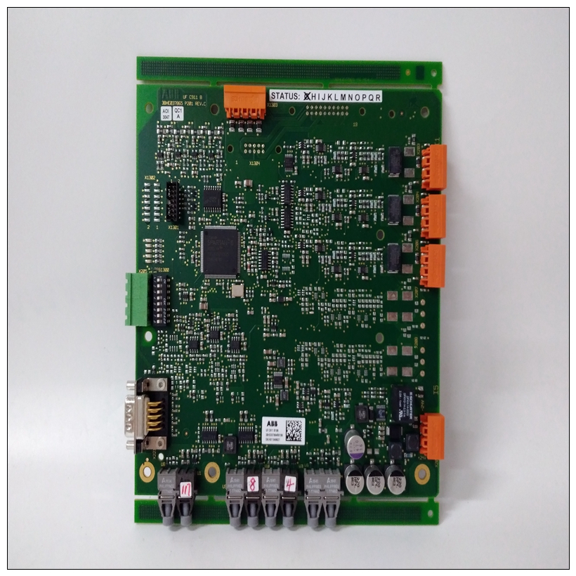
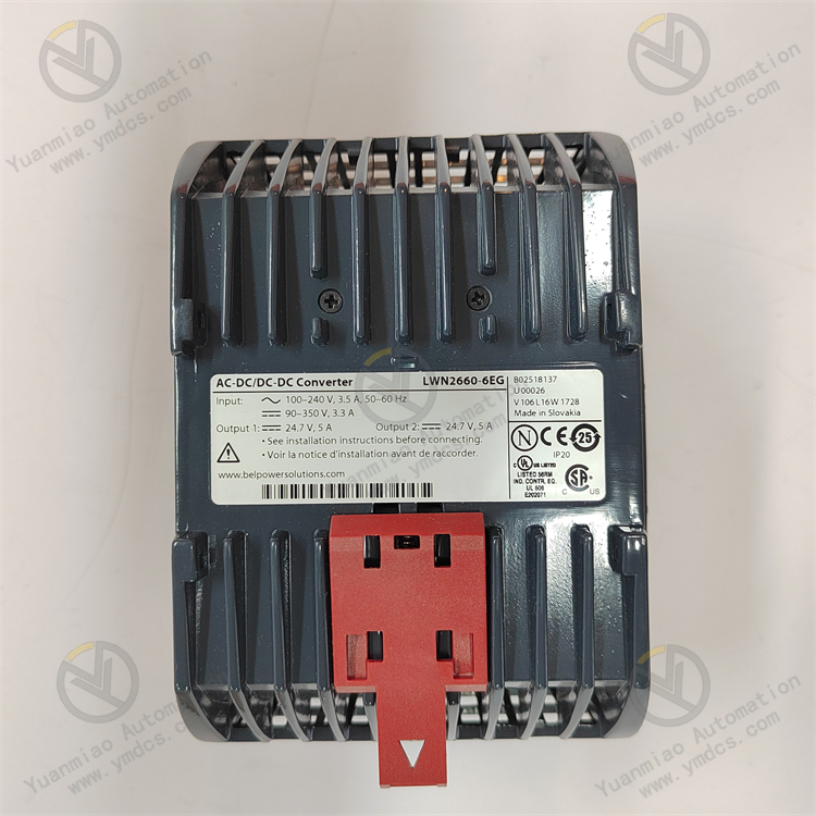
Full Model: LWN2660-6EG
Material Code: 3BHL000986P7002
Manufacturer: ABB
Product Name: High-Voltage Inverter Power Cell Module, Dedicated Inverter Cell for ACS6000 Medium-Voltage Drives
Product Positioning
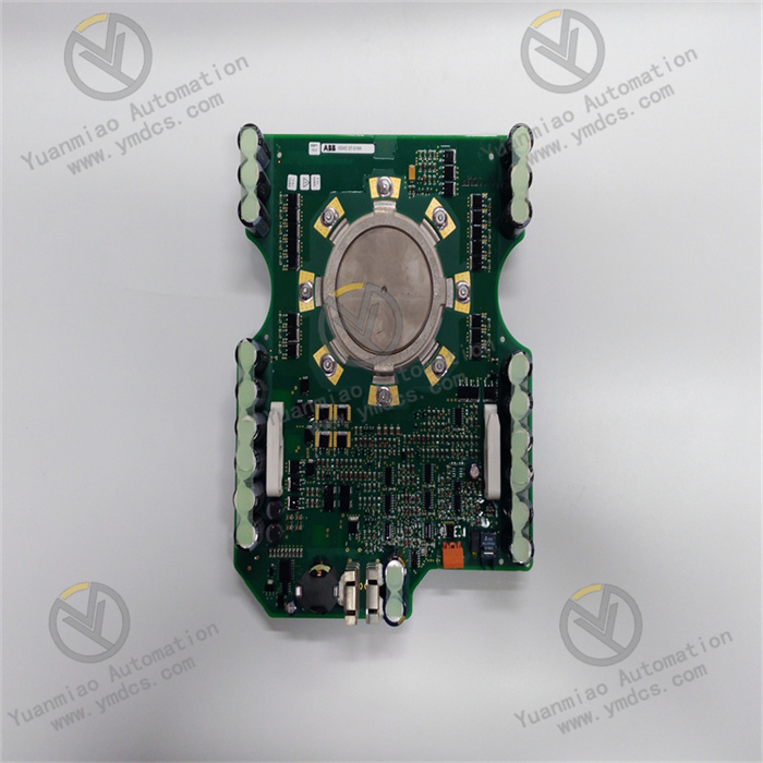
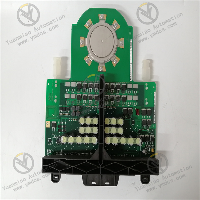
ABB LWN2660-6EG (3BHL000986P7002) serves as the core power inverter cell matched with ABB ACS6000 series medium-voltage high-power drives, and a critical power execution component of industrial high-voltage variable speed drive systems. Designed for 6kV/10kV medium-voltage variable frequency applications, this power cell adopts a modular cascaded topology. It integrates power semiconductor devices, drive circuits, signal sampling circuits, snubber protection circuits, communication detection circuits and other complete functional circuits. Featuring high withstand voltage, high power density, reliable operation and outstanding fault tolerance, it is widely deployed for variable speed control of large high-voltage motors in energy-intensive industries including power generation, metallurgy, chemical engineering and cement. It acts as a core component ensuring stable speed regulation and long-term continuous operation of medium-voltage drive systems.
Core Function
As the basic inverter module of ACS6000 medium-voltage drives, multiple cascaded power cells superpose to generate adjustable high-voltage variable frequency voltage. It converts DC voltage output from the rectifier side of the drive into AC voltage with continuously adjustable frequency and amplitude, providing smooth variable frequency driving power for high-voltage asynchronous motors and synchronous motors. The cell incorporates comprehensive protection mechanisms including overvoltage, overcurrent, overtemperature, short-circuit and phase loss protection. It monitors the operating status and electrical parameters of power devices in real time and rapidly isolates fault points to prevent complete unit shutdown caused by single-cell failure. It effectively realizes soft start and stepless speed regulation of high-power loads, reduces energy consumption and suppresses grid harmonics. It guarantees stable, efficient and safe operation of high-voltage motors and driven equipment, meeting the speed regulation and energy-saving requirements of industrial continuous production processes.
Applicable Systems
Exclusively compatible with the full series of ABB ACS6000 medium-voltage drives, including 6kV and 10kV high-power high-voltage variable speed drive systems. It perfectly matches the original equipment topology, control program, drive logic and communication protocol. It can seamlessly cooperate with the drive main control board, optical fiber communication board, rectifier cell, bypass cell and cooling system. It supports on-site replacement of identical cells and redundant switching upon faults. It boasts excellent compatibility and interchangeability between new and legacy equipment, applicable to new unit assembly, retrofit of old facilities, spare parts replacement after failures, unit capacity expansion and other scenarios.
Application Scenarios
Widely applied to variable speed control of large high-voltage motors in thermal power generation, iron & steel metallurgy, petrochemical industry, building materials & cement, mining & coal, large-scale water treatment and other sectors. Typical applications include variable frequency control of high-voltage auxiliary equipment such as boiler induced draft fans, forced draft fans, primary air fans, circulating water pumps, dust removal fans, blast furnace fans, sinter main exhaust fans, large compressors, slurry pumps and feed water pumps. It adapts to harsh industrial operating conditions characterized by high power, heavy load, 24-hour uninterrupted continuous operation and strict reliability requirements.
2. Technical Features
High-Voltage Robust Design with High Power DensityAdopting industrial-grade high-voltage dedicated power devices and insulating encapsulation technology, it adapts to operating conditions of high voltage and large current in medium-voltage variable frequency systems. Each cell offers large power capacity, high voltage withstand capability and strong load adaptability. The highly integrated module integrates the main inverter circuit, drive circuit, sampling circuit, protection circuit and communication interface into one unit. It greatly simplifies the overall structure of the drive, improves equipment power density, reduces overall footprint and weight, and satisfies the layout requirements of large and medium-sized high-voltage variable frequency equipment.
Multi-Level Electrical Protection for Safe and Reliable OperationThe cell is equipped with comprehensive dual hardware and software protection mechanisms, covering DC overvoltage, DC undervoltage, output overcurrent, instantaneous short circuit, module overtemperature, current unbalance, pulse abnormality and other protection functions. It delivers fast fault response and accurate action thresholds. Fault blocking and pulse blocking can be completed within microseconds to cut off fault output and accurately isolate faulty power cells. It effectively avoids risks such as power device breakdown, cell burnout, complete unit tripping and overload damage, and significantly improves operational safety and fault tolerance of high-voltage drive systems.
Optical Fiber Isolated Communication with Superior Anti-Interference PerformanceSignal interaction between the main control system and power cells is realized via a full optical fiber isolated communication architecture, abandoning traditional electrical signal transmission. It completely isolates industrial interference sources including strong electrical disturbance, electromagnetic radiation, ground potential difference and line crosstalk. Control signals are transmitted stably without delay or distortion. It effectively eliminates signal false triggering, command loss and communication exceptions under high-voltage strong electromagnetic environments, ensuring accurate speed regulation logic and stable control timing of the drive system.
Smooth Inverter Output with Excellent Speed Regulation PerformanceSupported by high-precision PWM pulse modulation technology combined with superposed output of cascaded multiple cells, it generates AC voltage with extremely high sinusoidal quality, low waveform distortion rate and minor harmonic components. It effectively suppresses motor heating, noise and torque ripple, and prevents high-voltage motor insulation aging and damage caused by shaft current. It supports smooth stepless speed regulation from zero speed to rated speed with stable start-stop performance and high speed regulation accuracy, perfectly meeting high-precision and high-stability speed control demands of high-power loads.
High-Efficiency Heat Dissipation Design for Continuous Full-Load OperationThe module adopts a customized forced air cooling structure with dedicated air ducts, paired with high thermal conductivity insulating substrates and high-efficiency heat dissipation components. It features high heat dissipation efficiency, low thermal resistance and uniform temperature rise. It can withstand harsh working conditions including long-term full-load operation, heavy load fluctuation and frequent start-stop. It restrains thermal degradation of power devices and avoids overtemperature alarms and overtemperature tripping. It supports 7×24-hour uninterrupted full-load continuous operation with outstanding durability and wide adaptability to various operating conditions.
Modular Standardized Design for Convenient Operation & MaintenanceThe standardized universal modular structure enables easy assembly and disassembly, strong interchangeability and wide compatibility. Faulty cells can be detached and replaced independently without modifying overall wiring and topology or disassembling and commissioning the whole unit. Built-in status monitoring and fault self-diagnosis functions can accurately report fault type, fault location and operating parameters, enabling maintenance personnel to quickly locate faults and eliminate hidden dangers. It greatly shortens equipment downtime for maintenance and reduces maintenance costs and production losses.
- Low Harmonics & High Energy Efficiency Complying with Grid StandardsThe cell delivers excellent inverter output waveform quality. Combined with the cascaded topology of the complete drive, it effectively suppresses grid harmonics and meets GB/T and IEC power quality standards without additional large-capacity filter devices. Motors operate at high efficiency with low reactive power loss, which significantly cuts energy consumption of high-voltage auxiliary equipment. It caters to industrial energy-saving renovation aiming at cost reduction and efficiency improvement, bringing remarkable economic benefits during long-term operation.
3. Specification Parameters
| Item | Parameter |
|---|---|
| Equipment Model | LWN2660-6EG |
| Material Code | 3BHL000986P7002 |
| Manufacturer | ABB |
| Equipment Type | Medium-Voltage Drive Power Inverter Cell, High-Voltage Variable Frequency Power Module |
| Compatible Equipment | ABB ACS6000 Series 6kV / 10kV Medium-Voltage High-Power Drives |
| Application Scope | Variable speed control, energy-saving renovation, soft start and load regulation of high-voltage fans, water pumps and compressors in power plants, chemical industry, metallurgy, cement and other industries |
| Cell Topology | Single-phase H-bridge inverter topology, superposed output via cascaded multiple cells |
| Rated DC Voltage | Matches standard DC bus voltage of ACS6000 system |
| Output Voltage Characteristic | PWM sinusoidal pulse width modulation, low-harmonic AC output with high sinusoidal quality |
| Communication Method | Full optical fiber isolated communication, resistant to strong electromagnetic interference |
| Cooling Mode | Forced air cooling with dedicated air duct structure |
| Core Protection Functions | DC overvoltage / undervoltage protection, output overcurrent protection, short-circuit protection, overtemperature protection, current unbalance protection, pulse abnormality protection, fault self-locking |
| Operating Temperature | -10℃~+55℃ |
| Storage Temperature | -40℃~+85℃ |
| Ambient Humidity | 5%~95%RH, non-condensing |
| Insulation Class | Industrial high-voltage reinforced insulation, suitable for medium-voltage heavy insulation conditions |
| Structural Feature | Standardized integrated modular structure, easy disassembly and strong interchangeability |
| Maintenance Feature | Fault self-diagnosis, real-time parameter monitoring, independent fault locking of single cell, replacement without overall commissioning |
| Equipment Characteristics | High voltage withstand, high-power output, low-harmonic inversion, optical fiber isolation anti-interference, multi-layer safety protection, continuous full-load operation, convenient maintenance, excellent energy-saving performance |
4. Working Principle
4.1 Power-On Initialization and Full-Range Self-Test
After the power cell is connected to the DC bus voltage of the drive, it automatically completes power-on initialization, hardware self-test, drive circuit detection, communication link matching and parameter loading. Internal detection circuits sequentially verify the operating status of power devices, drive pulse circuits, sampling circuits, optical fiber communication links and temperature detection modules, and troubleshoot hidden risks such as overvoltage risks, device abnormalities, circuit faults and communication failures. After passing self-test, an optical fiber communication link is established with the drive main control system, and the cell enters standby state to receive PWM modulation commands issued by the main controller at any time.
4.2 PWM Pulse Reception and Inversion Conversion
According to motor speed and load commands, the drive main control system sends high-precision PWM modulation pulse signals to each power cell via optical fiber. Upon receiving isolated pulse commands, this cell drives internal power switching devices to turn on and off in sequence, converting input DC voltage into single-phase AC voltage with adjustable amplitude and pulse width. Multiple identical power cells superpose outputs in accordance with cascaded topology to synthesize high-voltage, high-precision and low-harmonic three-phase AC power supply, realizing smooth variable speed regulation of high-voltage motors.
4.3 Real-Time Parameter Sampling and Status Monitoring
During operation, built-in high-precision sampling circuits continuously collect core parameters including DC bus voltage, output current, module temperature and operating status of switching devices. It monitors operating conditions such as load fluctuation, voltage deviation, current distortion and temperature rise in real time. All operating data is uploaded to the drive main control system via optical fiber, providing accurate data support for main control logic operation, speed regulation, load optimization and fault judgment.
4.4 Multi-Layer Fault Protection and Fault Isolation
Dual hardware and software protection mechanisms remain active throughout cell operation. Once overvoltage, undervoltage, overcurrent, short circuit, overtemperature, pulse abnormality or other faults are detected, drive pulses are blocked instantaneously and inverter output is cut off. Meanwhile, fault status is locked and fault codes and fault types are uploaded. Independent locking protection is triggered for single-cell faults to accurately isolate fault locations. Coordinated with the overall fault tolerance logic of the drive, bypass removal of faulty cells can be realized to prevent fault propagation of a single module leading to complete unit tripping and maximize continuous equipment operation.
4.5 Steady-State Speed Regulation and Energy-Saving Operation Control
Under normal load conditions, the power cell continuously executes accurate PWM inverter output. Combined with the cascaded multi-cell superposition technology of the whole drive, it outputs stable AC power with extremely low harmonics, effectively optimizing the operating state of high-voltage motors and reducing motor loss, noise and reactive power consumption. Output frequency and voltage are dynamically adjusted in real time according to changes of process load on site to achieve accurate stepless speed regulation matching process load requirements, realizing the control target of efficient energy-saving and stable equipment operation.
5. Common Problems and Solutions
5.1 Phenomenon: No fault alarm on cell, no output from drive, equipment fails to adjust speed
Possible Causes
① Loose optical fiber communication links of the cell, damaged optical fiber or abnormal transceiver;
② No DC bus input voltage on the cell and abnormal front-end rectifier circuit;
③ Fault of cell drive circuit leading to failure of normal pulse output;
④ Abnormal cell configuration parameters and failure to synchronize main control commands;
⑤ Open-circuit damage of internal power devices in the module.
Solutions
Power off the equipment and check tightness of optical fiber connectors on the cell. Clean optical fiber end faces, replace damaged optical fibers and reconnect communication links. Detect DC bus input voltage and troubleshoot faults of front-end rectifier cells and power supply circuits. Read fault codes from the drive main controller to locate abnormal power cells. Restart and synchronize cell configuration parameters and rematch main control communication protocols. If there is still no output after eliminating faults of external circuits and communication, hardware damage of the power cell is confirmed, and the original ABB LWN2660-6EG (3BHL000986P7002) power module shall be replaced.
5.2 Phenomenon: Frequent overvoltage / undervoltage alarms and tripping of power cell
Possible Causes
① Severe grid voltage fluctuation, instantaneous voltage drop or surge;
② Aging of cell bus buffer capacitors, capacity attenuation and degraded voltage stabilization performance;
③ Bus voltage oscillation triggered by sudden load change and frequent motor start-stop;
④ Deviation of cell voltage sampling circuit leading to inaccurate parameter sampling;
⑤ Unbalanced voltage distribution caused by abnormal operation of other cells in the string.
Solutions
Monitor grid operating voltage, avoid working conditions with drastic voltage fluctuation and install voltage stabilizers when necessary. Detect capacity and operating status of cell bus capacitors and replace aged and failed capacitors. Optimize equipment start-stop logic to reduce instantaneous load impact. Calibrate cell voltage sampling parameters and correct sampling offset errors. Inspect operating status of all cascaded cells and repair abnormal units. If alarms occur frequently without abnormal external conditions, module aging is confirmed and the original power cell needs to be replaced.
5.3 Phenomenon: Cell overtemperature alarm, high-temperature tripping and rapid temperature rise
Possible Causes
① Blocked cabinet air ducts, heavy dust accumulation on filter screens and insufficient cooling air volume;
② Heavy dust accumulation on cell heat dissipation substrate resulting in significantly reduced heat dissipation efficiency;
③ Long-term full-load or overload operation leading to excessive temperature rise of devices;
④ Faulty cooling fan with insufficient rotating speed or no air supply;
⑤ Aging of internal power devices of the cell and abnormally increased power consumption.
Solutions
Regularly power off to clean dust and debris on cabinet filter screens, air ducts and cell heat dissipation surfaces and unblock heat dissipation channels. Inspect operating status of cooling fans, replace faulty fans to guarantee rated cooling air volume. Reasonably control equipment load and avoid long-term overload operation. Detect cell temperature rise curve and device power consumption to locate abnormal heat sources. If overtemperature alarms and tripping still occur after cleaning the cooling system, aging and damage of internal components inside the module are confirmed and spare parts replacement is required.
5.4 Phenomenon: Output overcurrent and short-circuit alarms, motor vibration and unstable speed regulation
Possible Causes
① Aging high-voltage motor insulation, inter-turn short circuit of windings or load short circuit;
② Damaged output cables, ground leakage or phase-to-phase short circuit;
③ Performance degradation and abnormal conduction of output devices in power cell;
④ Fault of current sampling circuit and distorted sampling data resulting in false protection;
⑤ Instantaneous overcurrent caused by blocked load and excessive mechanical resistance.
Solutions
Power off to test insulation resistance and winding status of high-voltage motors and troubleshoot motor short circuit and leakage faults. Fully inspect insulation and continuity of high-voltage output cables and repair damaged lines. Calibrate cell current sampling parameters and troubleshoot sampling circuit faults. Turn the motor shaft manually to check mechanical status of the load and eliminate mechanical jamming resistance. If overcurrent alarms persist after eliminating load and line faults, damage of the inverter circuit inside the power cell is confirmed and the module shall be replaced.
5.5 Phenomenon: Optical fiber communication interruption, offline cell and abnormal overall speed regulation
Possible Causes
① Excessive bending of optical fiber, contaminated end faces or excessive optical attenuation;
② Aging optical fiber transceiving ports and reduced sensitivity;
③ Communication packet loss caused by strong electromagnetic interference inside the cabinet;
④ Fault of cell communication board and abnormal protocol parsing;
⑤ Mismatched parameters of main control communication link.
Solutions
Arrange optical fiber routing properly to avoid excessive bending and extrusion. Clean optical fiber end faces and replace optical cables with excessive attenuation. Inspect operating status of cell optical fiber transceiving ports and troubleshoot port aging faults. Optimize cabinet grounding and shielding measures to reduce electromagnetic interference. Resynchronize overall communication parameters and protocols to fix communication link abnormalities. If frequent offline status remains after rectification, communication function failure of the power cell is confirmed and the original ABB LWN2660-6EG power module needs to be replaced.