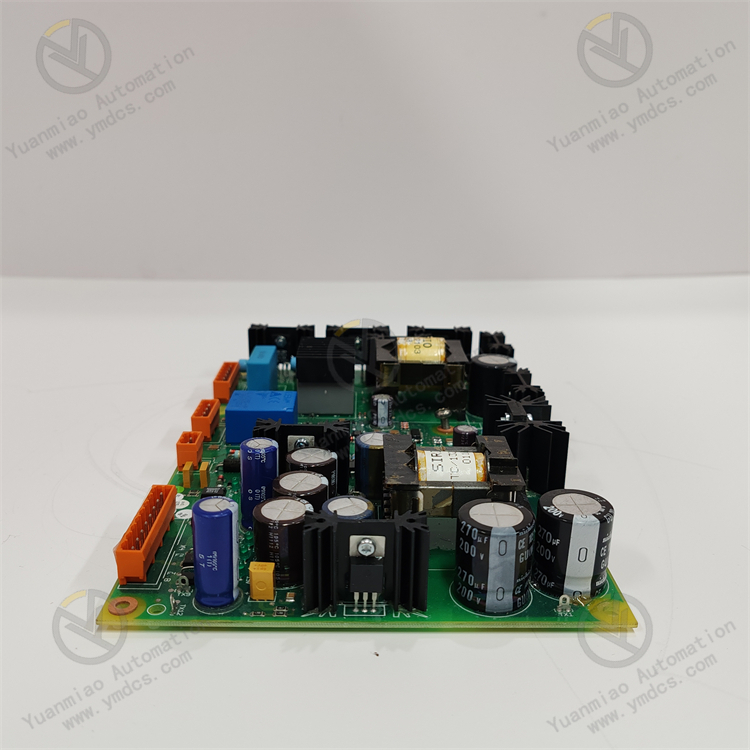
Description
1. Product Overview
Full Model: DYPS154C 61430001-YP
Manufacturer: ABB
Product Series: Special Power Conditioning & Mixed Signal Module Series for Advant OCS / Industrial IT Process Control Systems
Product Name: Integrated Rack-Mounted Stabilized Power Supply & Multi-Function Mixed I/O Module
Product Positioning
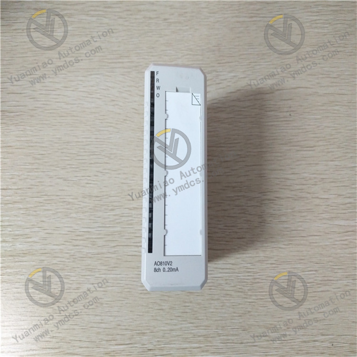
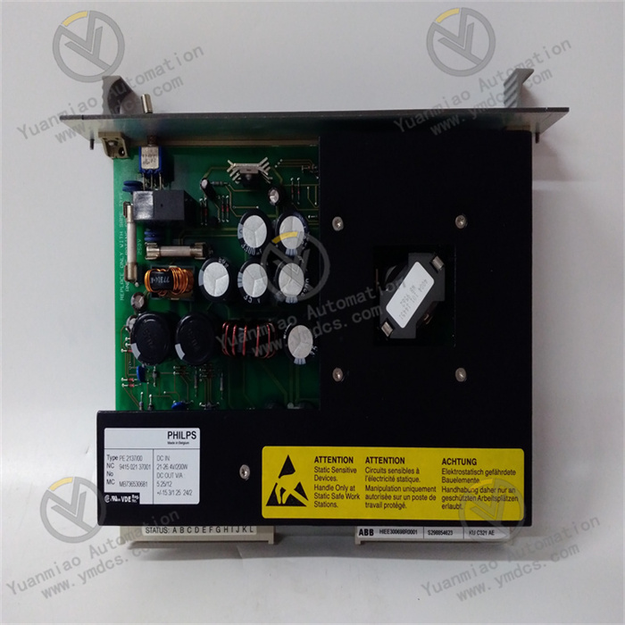
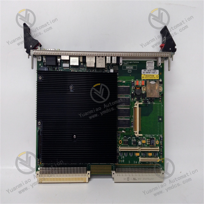
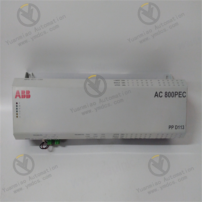
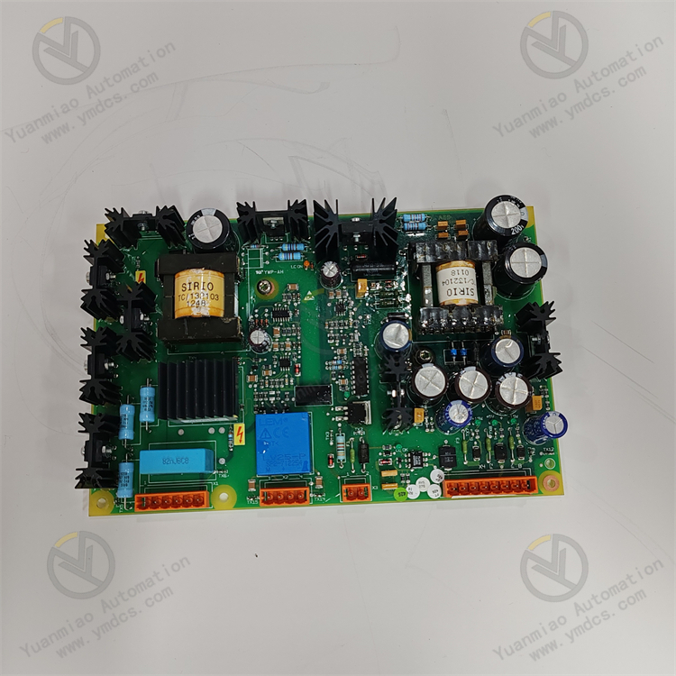
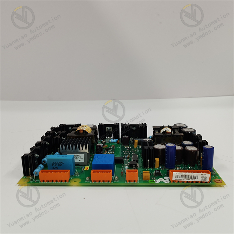
DYPS154C 61430001-YP is an integrated power and mixed signal module customized by ABB for Advant OCS and Industrial IT industrial process control systems. It serves as core supporting hardware for rack power stabilization, reference voltage output, multi-channel I/O signal acquisition and control within the DCS system. The module integrates high-precision voltage stabilizing circuits, configurable multi-channel digital I/O, analog input/output and high-speed counter units. It breaks the functional limitations of traditional standalone power modules or single-function I/O modules, integrating power regulation, signal conditioning, data acquisition and logic output into one unit. Adopting an industrial-grade DSP main control chip and multi-layer isolation protection architecture, it is suitable for demanding industrial environments such as power, chemical and metallurgy with continuous operation and complex electromagnetic interference. It can supply clean reference power steadily to sub-modules inside the rack while acquiring and regulating multiple field process signals. It is widely applied in engineering scenarios including new cabinet assembly, legacy system power module upgrading, I/O point expansion and integrated equipment technical retrofits.
Core Functions
The module undertakes six core responsibilities: stabilized power supply for system racks, isolated reference voltage output, programmable multi-channel digital signal input/output, high-precision analog signal acquisition and transmission, high-speed pulse counting, and module-level fault self-diagnosis and power protection. It can simultaneously provide stable power for local rack peripherals and small field sensors. It supports acquisition of various analog signals including voltage, current and RTD signals, and enables bidirectional configuration of 24 VDC digital channels. The built-in high-speed counter satisfies condition monitoring of pulse-based equipment. Embedded multi-protection mechanisms against overvoltage, overcurrent, short circuit and surge automatically filter power noise and suppress voltage fluctuations. It delivers clean and stable operating power to the control system and realizes accurate real-time interaction of process signals, ensuring safe power supply, precise signal acquisition and reliable equipment linkage. It effectively reduces the number of modules in cabinets and wiring complexity.
Compatible Systems
Fully compatible with the complete range of ABB Advant OCS and Industrial IT process control systems. Designed for installation in standard rack slots, it can seamlessly network and cooperate with system main control CPUs, various I/O acquisition modules and communication modules. Natively compatible with all versions of ABB Control Builder configuration software. It supports customized I/O mode configuration, power parameter calibration, counter parameter debugging, online status monitoring and parameter modification. The module supports non-destructive hot-swappable in-situ replacement with comprehensive backward compatibility. No modification to main control logic or cabinet wiring is required for new and existing systems; only simple parameter matching is needed for commissioning. It adapts to various retrofit projects such as replacement of aging modules in legacy systems, system point expansion and power supply system optimization.
Application Scenarios
Primarily deployed in facilities equipped with ABB industrial control systems, including thermal power, hydropower, oil & gas chemical plants, metallurgical heavy industry, intelligent manufacturing automatic production lines and municipal energy management. Typical applications cover auxiliary power supply inside cabinets, stabilized power supply for small field sensors, RTD temperature signal acquisition, analog monitoring of process voltage/current, discrete interlock control for equipment start/stop, high-speed pulse counting and analog regulation of small actuators. Capable of long-term operation under harsh industrial conditions including wide temperature variation, dust and humidity, mechanical vibration, variable frequency electromagnetic interference and power fluctuation. It provides an integrated power and signal acquisition solution for small and medium automation systems, simplifying cabinet layout and improving overall system stability.
2. Technical Features
Integrated Power & I/O Design, High Integration to Save Space
A single module incorporates high-precision stabilized power units, multi-channel digital I/O, analog input/output and high-speed counting functions. It consolidates functions traditionally distributed among separate power modules, signal acquisition modules and counter modules. It significantly reduces rack slot occupancy, simplifies internal wiring, lowers assembly and maintenance costs, and fits compact cabinet layouts and expansion retrofits of legacy systems.
High-Precision Stabilized Output, Clean and Reliable Power Supply
Equipped with dedicated voltage regulation chips and multi-stage filter circuits, it effectively suppresses industrial grid voltage fluctuations, high-frequency noise and surge interference. It delivers output voltage with high accuracy and low ripple, supplying clean and stable operating power to low-voltage rack modules and precision field sensors. It eliminates signal drift, module restart and equipment misoperation induced by unstable power supply.
Versatile Mixed I/O with Strong Programmability
Integrates configurable digital input/output, multi-type analog interfaces and high-speed counter units. Digital channels support bidirectional custom configuration. Analog channels accept voltage, current, Pt100/Pt1000 RTD signals, covering most industrial process signals for temperature, pressure, flow, switch status and pulse speed. No additional adapter modules are required, providing universal compatibility for diverse measuring points.
Multi-Layer Electrical Isolation & Safety Protection, Excellent Environmental Adaptability
Independent galvanic isolation is implemented for power circuits, analog channels and digital channels to avoid crosstalk between circuits. Built-in multi-protection against overvoltage, overcurrent, short circuit, over temperature, surge and electrostatic discharge. Compliant with industrial EMC standards, it effectively resists high-frequency interference from inverters, electromagnetic radiation during motor start-stop and line surge shocks. No power anomalies, signal bouncing or module damage occur under complex operating conditions.
High-Speed DSP Main Controller for Accurate and Fast Acquisition
Adopts an industrial high-performance DSP processor featuring high sampling rate and fast computation. Analog acquisition resolution reaches 12 bits (including sign bit), enabling precise capture of subtle variations in process signals. The built-in high-speed counter supports multi-mode pulse acquisition to meet real-time and accuracy requirements for high-precision process monitoring and high-speed equipment condition statistics.
Full-Range Intelligent Self-Diagnosis for Efficient Maintenance
Three-tier self-diagnosis covering power level, module level and channel level continuously monitors potential risks including supply voltage, load current, module temperature, channel faults and bus communication abnormalities. Independent LED status indicators on the front panel directly display power operation status, channel working status and fault types. Fault codes are uploaded to the upper system in real time to achieve accurate fault localization and greatly shorten troubleshooting and handling time.
Industrial Wide-Temperature Ruggedization for Long-Term Reliable Operation
Constructed with industrial reinforced PCB and wide-temperature anti-aging components enhanced with moisture-proof, dust-proof, vibration-proof and shock-resistant processes. Stable operation is guaranteed across an extended temperature range. It withstands alternating temperature and humidity, dust accumulation and continuous mechanical vibration on site. Supporting 24/7 uninterrupted operation, no power drift, channel attenuation or parameter loss occurs after long service life.
3. Specification Parameters
| Item | Parameter |
|---|---|
| Model | DYPS154C 61430001-YP |
| Manufacturer | ABB (ABB Group, Switzerland) |
| Product Series | Power Supply & Mixed I/O Module for Advant OCS / Industrial IT Process Control System |
| Module Type | Integrated Stabilized Power Supply Module, Multi-Function Mixed Signal Acquisition & Output Module |
| Applicable Systems | Complete ABB Advant OCS and Industrial IT Process Control Systems |
| Configuration Software | All versions of ABB Control Builder |
| Core Hardware | High-performance industrial DSP main controller, on-board high-speed memory and data buffer |
| Digital Channels | 8 configurable 24 VDC digital input/output channels; max. load 0.5 A per channel |
| Analog Input Channels | 4 universal analog inputs, compatible with voltage, current, Pt100/Pt1000 RTD signals |
| Analog Output Channels | 2 universal analog outputs, supporting voltage and current signals |
| Signal Resolution | 12-bit (including sign bit) high-precision acquisition and output |
| Functional Unit | Integrated configurable high-speed counter supporting multi-mode pulse acquisition |
| Reference Power Supply | 6 reference voltage branches; max. current 0.5 A per branch; built-in 2 A branch fuse protection |
| System Power Supply | Standard industrial 24 VDC, compatible with conventional industrial control power infrastructure |
| Power Consumption | ≤5 W at no load; ≤20 W at full load |
| Operating Temperature | -25℃~+70℃ (Extended industrial temperature range) |
| Storage Temperature | -40℃~+85℃ |
| Ambient Humidity | 5%~95%RH, non-condensing, suitable for humid and dusty industrial environments |
| Protection Class | IP20 (module body) |
| Mounting Method | Snap-in installation in standard Advant OCS rack slots |
| Weight | Approx. 300 g, compact lightweight design |
| Isolation & Protection | Independent galvanic isolation for power, analog and digital circuits; anti-crosstalk, common-mode interference suppression, multi-stage surge and ESD protection |
| O&M Features | Three-tier full-range self-diagnosis, LED status indication, online parameter configuration, hot-swappable in-situ replacement, upload and traceability of fault codes |
| Product Characteristics | Integrated power & I/O, high-precision acquisition, multi-signal compatibility, wide-temperature operation, multi-layer protection, low power consumption, convenient maintenance |
4. Working Principle
4.1 Power-On Initialization and Full-Range Self-Test
After stable 24 VDC power supply is connected, the module automatically completes hardware initialization, DSP startup, firmware loading, bus protocol matching and parameter reset. It performs comprehensive self-test on voltage stabilizing circuits, reference voltage branches, all I/O channels, isolation circuits, high-speed counter units and bus communication modules to detect hidden issues such as abnormal power supply, branch short circuit, channel failure, circuit damage and bus disconnection. Once self-test passes, the module synchronizes system configuration parameters, I/O settings, counter modes and power protection thresholds automatically. After signal calibration and power regulation adaptation, it enters normal power supply and signal acquisition mode.
4.2 Power Conditioning and Protected Branch Output
External industrial control power enters the module and first passes multi-stage filtering, voltage regulation and surge suppression circuits. High-frequency grid noise, voltage spikes and fluctuations are filtered to generate high-precision, low-ripple clean reference power. Stabilized power is delivered via six independent output branches. Each branch is equipped with independent current limiting and fuse protection. In case of overload or short circuit, power is cut off rapidly to prevent fault propagation. It provides stable and safe operating power for small rack-mounted modules and precision field sensors to ensure consistent operation of peripherals.
4.3 Isolated Signal Acquisition and Waveform Conditioning
Field process signals including temperature, pressure, flow, switch status and pulse speed are connected to corresponding analog, digital and counter channels. All incoming signals undergo preprocessing including independent galvanic isolation, voltage filtering and waveform shaping. The circuit blocks external electromagnetic interference, ground potential difference and line crosstalk, correcting signal distortion and noise jitter. Processed standard signals are transmitted to the DSP unit. A 12-bit high-precision sampling algorithm performs signal decoding, value conversion and logic judgment to accurately restore real operating conditions and process parameters of field equipment.
4.4 Programmable I/O Logic Operation and Analog Output Regulation
Based on preconfigured logic, digital channels execute custom input acquisition or output control to realize equipment start/stop, interlock feedback and status monitoring. Analog channels achieve precise process parameter acquisition, value conversion and linear temperature compensation. Meanwhile, standard voltage/current analog signals are output according to system commands to drive small field regulating valves and variable frequency actuators for closed-loop process control. The high-speed counter unit continuously analyzes pulse signals to calculate high-frequency data such as rotational speed, flow rate and displacement.
4.5 Data Aggregation and System Interaction
The module aggregates acquired analog values, digital status, pulse counting data and power operating parameters in real time. Data is uploaded to the main control CPU via the high-speed backplane bus within milliseconds to refresh the system image area. Upper SCADA systems access these data for real-time monitoring, data logging, trend analysis and fault alarming. At the same time, the module accurately receives control commands and parameter adjustment instructions from the system, executing I/O output and power regulation quickly to achieve seamless synchronization between field equipment and the control system.
4.6 Continuous Fault Monitoring, Intelligent Protection and Traceability
Three-tier self-diagnosis and intelligent protection remain active throughout operation. The module continuously monitors supply voltage, load current, module temperature, branch conditions, channel status and bus communication quality. It accurately identifies faults including power overvoltage/undervoltage/overcurrent, branch short circuit, channel abnormality, signal out-of-range, intermittent communication and module overheating. Corresponding protection actions are triggered, front-panel alarm LEDs are activated, and dedicated fault codes are uploaded to the upper system. Real-time alarm, precise localization and full traceability of faults enable maintenance staff to troubleshoot rapidly and restore normal system operation.
5. Common Faults and Troubleshooting
5.1 Symptom: No response after power-on; undetected by system; power LED off
Possible Causes
① Module not fully latched; poor rack contact; oxidized and dusty backplane contacts;
② Abnormal 24 VDC system power supply, missing voltage or excessive voltage drop;
③ Blown fuse or damaged power circuit inside the module;
④ Loss of module firmware parameters and initialization failure;
⑤ Mismatched firmware versions between module and control system.
Solutions
Power off the system, reinsert and lock the module securely. Clean oxidation and dust on backplane contacts to ensure reliable connection. Measure supply voltage with a multimeter, troubleshoot upstream power modules and wiring to restore standard 24 VDC supply. Inspect main and branch power circuits, replace blown fuses and repair power faults. Re-download module configuration parameters, restore factory settings and reconfigure. Verify and upgrade firmware to compatible revisions. If no response persists after eliminating external issues, internal hardware failure is confirmed; replace with original DYPS154C 61430001-YP module.
5.2 Symptom: No output from reference power branches; abnormal power supply to peripherals
Possible Causes
① Branch overload or line short circuit triggering protection lockout;
② Blown branch fuse leading to power interruption;
③ Insulation damage and leakage on peripheral wiring;
④ Aging voltage regulation circuit inside the module causing abnormal output;
⑤ Incorrect branch parameter configuration; power output function disabled.
Solutions
Disconnect branch loads, troubleshoot short circuit, leakage and overload faults and repair wiring. Inspect corresponding branch fuses and replace blown components. Power cycle the module to clear protection lockout and restore branch power. Enter configuration software to verify branch power parameters and enable stabilized output. Check peripheral equipment to avoid secondary overload. If the branch still has no output after rectification, hardware failure of the internal power circuit is confirmed; replace the module.
5.3 Symptom: Analog readings drift, fluctuate heavily or show abnormal accuracy
Possible Causes
① Severe on-site electromagnetic interference; unshielded cables and non-standard grounding;
② Loose sensor terminals and signal attenuation due to aging cables;
③ Incorrect configuration of range, temperature compensation and filtering parameters;
④ Degraded performance of analog channel isolation and filter circuits;
⑤ Abnormal module operating temperature leading to measurement drift.
Solutions
Replace with shielded signal cables, implement single-point grounding and route cables away from strong interference sources such as inverters and high-power motors. Tighten sensor terminals and replace aged wiring. Recalibrate analog ranges, temperature compensation and anti-jitter filtering parameters to match field equipment. Improve cabinet ventilation to avoid high-temperature drift. Enable channel filtering and averaging algorithms to stabilize readings. If accuracy remains unsatisfactory after optimization, channel hardware aging is confirmed; replace the spare module.
5.4 Symptom: False triggering, status bouncing and uncontrolled output on digital channels
Possible Causes
① Induced noise and excessive leakage current on wiring caused by field interference;
② Improper setting of digital channel debounce and threshold parameters;
③ Port protection lockout triggered by short circuit or overload of external loads;
④ Aging I/O drive circuits on the module;
⑤ Poor cabinet grounding resulting in severe common-mode interference.
Solutions
Optimize field wiring and grounding to reduce leakage current and induced noise. Adjust digital channel debounce delay and level threshold parameters in configuration software to enhance anti-interference capability. Troubleshoot external load faults, eliminate short circuit and overload risks, and power cycle to release port protection. Improve cabinet grounding to suppress common-mode interference. If bouncing and uncontrolled output remain after parameter and wiring rectification, damaged I/O port hardware is confirmed; replace the module.
5.5 Symptom: Inaccurate high-speed counting, missing pulses and chaotic counting values
Possible Causes
① Insufficient pulse amplitude and distorted waveform;
② Mismatched counting mode and sampling frequency parameters with field equipment;
③ Spurious pulses induced by line interference causing false counting;
④ Performance degradation of the high-speed counter hardware unit;
⑤ Unstable pulse output from the sensor.
Solutions
Measure pulse waveform and amplitude, replace faulty sensors and optimize signal wiring. Reconfigure counting mode, sampling rate and filtering parameters to match pulse characteristics of field equipment. Add pulse filtering and waveform conditioning to suppress false noise pulses. Secure wiring to avoid disturbance-induced signal fluctuation and calibrate counter parameters. If counting errors continue after rectification, hardware failure of the counter unit is confirmed; replace with original module.