Description
1. Overview
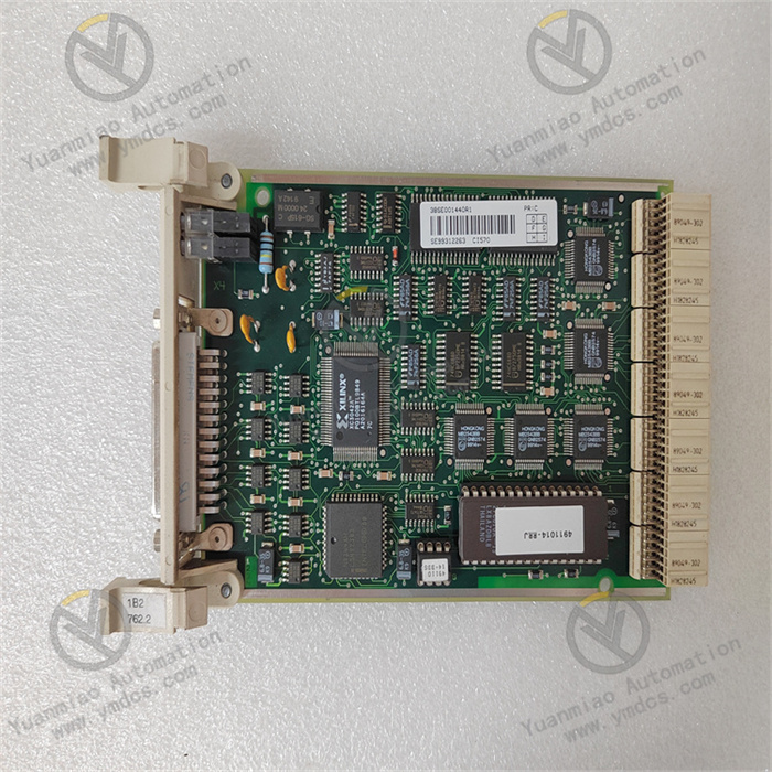
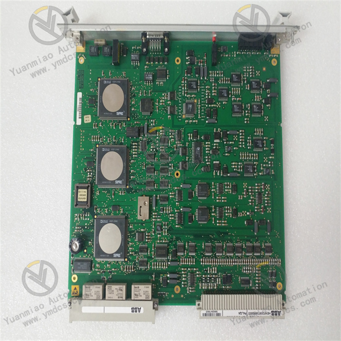
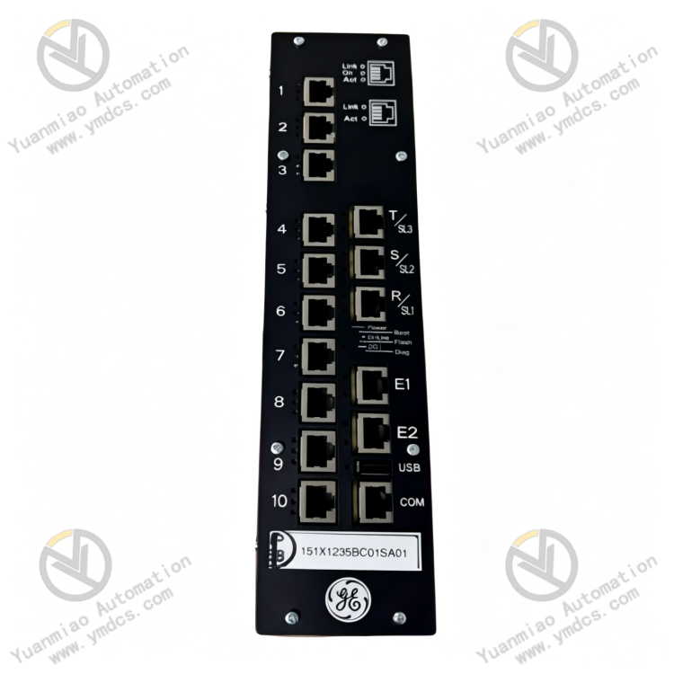
151X1235BC01SA41 is a VersaMax‑series bus expansion communication module manufactured by General Electric (GE). Developed for the VersaMax PLC control system, it serves as core communication hardware for local I/O bus expansion, remote‑station networking and multi‑module cascading capacity expansion. Adopting the VNET differential bus architecture, the module enables high‑speed data exchange between the PLC main controller and distributed I/O modules. It is widely deployed in industrial‑automation control systems for power, metallurgy, chemical, water‑treatment and intelligent‑manufacturing sectors, and fits I/O‑capacity expansion and bus‑networking scenarios for small‑and‑medium‑sized production lines, complete sets of equipment and distributed measurement‑and‑control sites.
Designed with industrial‑grade RS‑485 differential communication, this module features high transmission speed, strong anti‑interference performance, stable multi‑module cascading and long transmission distance. It supports serial cascading networking of multiple modules to greatly expand the I/O point capacity of the PLC system. Integrated with hardware‑based bus self‑test, link‑fault diagnosis and data fault‑tolerant‑check functions, it supports long‑term non‑stop continuous operation and adapts to harsh on‑site industrial conditions including electromagnetic interference, alternating temperature‑humidity and dense‑equipment layout. It is a key spare part for legacy‑bus retrofitting, I/O‑loop capacity expansion and remote‑substation construction of VersaMax systems.
2. Functions and Features
2.1 Core Functions
VNET High‑speed Bus Data Exchange: Based on GE proprietary VersaMax VNET bus protocol and RS‑485 differential‑transmission mechanism, it realizes command distribution, status feedback and parameter interaction between the PLC main controller and expanded I/O modules, ensuring real‑time, delay‑free and jitter‑free system data synchronization.
Multi‑module Multi‑level Cascading Capacity Expansion: Supports cascading and networking of up to 20 I/O modules on a single link. It flexibly expands system input‑and‑output points and breaks the local‑I/O‑capacity limit of the main controller, suiting the construction of large‑scale distributed I/O architectures and capacity‑expansion retrofits of legacy systems.
Long‑distance Stable Communication: Differential‑signal transmission delivers strong anti‑attenuation capability. The maximum bus‑link transmission distance reaches 200 m, meeting distributed measurement‑and‑control networking requirements for cross‑zone workshops, long‑range equipment and remote substations.
High‑speed Baud‑rate‑adaptive Communication: Supports a maximum bus baud rate of 1.2 Mbps and system‑adaptive rate matching. It balances high‑speed data transmission and long‑distance communication stability and effectively avoids data‑refresh stalling and packet loss for large‑volume I/O data.
Bus‑link Self‑diagnosis and Fault Tolerance: Real‑time monitoring of bus‑link on‑off status, signal attenuation, packet loss and module offline events. It accurately pinpoints abnormal points and uploads fault information. Equipped with data fault‑tolerant‑check capability, normal system operation can be maintained under minor‑signal‑interference conditions.
Plug‑and‑play Automatic Addressing: Compatible with VersaMax system bus topology. After being connected to the link, the module automatically completes addressing, protocol matching and parameter synchronization without complex manual configuration, simplifying on‑site networking‑commissioning procedures and lowering operation‑and‑maintenance difficulty.
All‑weather Continuous‑operation Control: Hardware circuits are optimized for industrial conditions. It supports 7×24‑hour non‑stop operation and satisfies stable‑operation requirements for continuous‑production production lines and unattended automatic‑control systems.
2.2 Product Characteristics
Differential Transmission with Excellent Anti‑interference Performance: Industrial‑grade RS‑485 differential‑communication architecture effectively suppresses on‑site high‑frequency harmonics, electromagnetic crosstalk, static interference and line noise. It prevents data jitter, communication interruption and module offline anomalies for heavy‑EMI factory environments.
Flexible Networking and Low Capacity‑expansion Cost: Supports chained multi‑level cascading. Mass‑scale I/O‑point expansion can be realized without adding extra main‑controller units. Simple topology and convenient wiring substantially reduce system‑expansion and retrofitting costs.
High‑speed Transmission and Low Latency: Maximum bus transfer rate of 1.2 Mbps delivers fast data refresh and ultra‑low latency, precisely fitting high‑precision‑control scenarios such as logic control, sequence‑based linkage and closed‑loop regulation.
Industrial‑grade High Stability and Reliability: Adopts industrial‑grade components. Circuits feature anti‑aging, shock‑resistance and tolerance to alternating temperature‑humidity. No communication drift or protocol disorder occurs during long‑term service, yielding low equipment‑failure rates.
Native System Compatibility and Wide Adaptability: Natively compatible with the full range of GE VersaMax PLC and I/O modules. Bus protocols, addressing logic and communication mechanisms are fully matched. It is plug‑and‑play upon replacement without program or configuration‑parameter modification.
Convenient Operation‑Maintenance and High Fault Tolerance: Built‑in bus‑fault self‑diagnosis delivers accurate fault‑location. Hot‑swap and non‑shutdown maintenance are supported. Single‑module faults will not disrupt core operation of the whole bus link, guaranteeing production continuity.
3. Specifications
| Item | Specifications |
|---|---|
| Model | 151X1235BC01SA41 |
| Device Type | VersaMax VNET Bus Expansion Communication Module |
| Brand‑Manufacturer | GE (General Electric) |
| Applicable System | GE VersaMax PLC Control System |
| Bus Type | VNET Bus (RS‑485 Differential Transmission) |
| Maximum Baud Rate | 1.2 Mbps |
| Max. Cascaded Modules per Link | 20 I/O modules |
| Maximum Bus Transmission Distance | 200 m |
| Communication Features | Differential anti‑interference, data fault‑tolerant check, adaptive rate matching |
| Addressing Mode | Bus automatic addressing, plug‑and‑play |
| Operating Temperature | 0 ℃ ~ +60 ℃ (standard industrial condition) |
| Storage Temperature | ‑40 ℃ ~ +85 ℃ |
| Ambient Humidity | 5%‑95%RH, non‑condensing |
| Mounting Method | Standard DIN‑rail mounting, rack‑slot mounting |
| Operating Features | 7×24‑hour continuous‑operation support, hot‑swap maintenance, fault self‑diagnosis |
4. Operating Principle
The 151X1235BC01SA41 bus‑expansion communication module operates on the VNET differential‑bus closed‑loop‑communication mechanism. Upon power‑on, it automatically completes hardware self‑test, bus‑protocol initialization, link scanning and device addressing, synchronizes communication parameters with the VersaMax main controller, and establishes a stable bus‑communication link.
During operation, as a core expansion unit of the bus link, the module relays bidirectional‑data interaction between the main controller and cascaded I/O modules. Logic commands, parameter configurations and control signals issued by the main controller are forwarded through this module to downstream I/O units. Meanwhile, operating status, point‑signal data and fault information of each‑substation I/O module are collected in real‑time, packed‑and‑checked and uploaded back to the PLC main controller to implement system closed‑loop control and status monitoring. Leveraging RS‑485 differential‑transmission characteristics, common‑mode interference and signal attenuation on cables are effectively counteracted to guarantee data‑transmission accuracy for long‑distance multi‑node networking.
Embedded data‑check‑and‑fault‑tolerance algorithms perform real‑time data‑verification and error correction to avoid packet loss and code errors induced by electromagnetic interference. Bus‑link status, node‑online status and communication‑rate stability are continuously monitored. Once link disconnection, module offline or data abnormality is detected, fault nodes are latched and alarm information is uploaded, while communication of healthy nodes remains unaffected to prevent full‑system shutdown. After fault clearance, the module automatically reconnects and synchronizes data to rapidly restore normal bus communication.
5. Application Scenarios
I/O‑capacity‑expansion Retrofit for VersaMax PLC Systems: Solves insufficient local‑I/O‑point issues of legacy VersaMax systems. Bus‑cascading expands I/O capacity without main‑controller replacement, enabling low‑cost system‑upgrade‑and‑expansion for production‑line retrofits and new‑process‑point addition.
Distributed Remote‑I/O Networking: Leverages the 200‑meter long‑distance‑transmission capability to build distributed remote measurement‑and‑control workshops, fitting automated production lines, assembly‑line equipment and complete automatic‑control systems with scattered and geographically‑dispersed equipment layout.
Chemical / Water‑treatment Automatic‑control Systems: Deployed in continuous‑process scenarios including chemical processes, sewage treatment and pure‑water preparation. It stably realizes multi‑point analog‑and‑discrete‑signal acquisition and equipment control to assure long‑term non‑stop system operation.
Metallurgy‑and‑power‑industry Measurement‑and‑control: Adapts to heavy‑EMI operating conditions in metallurgy and power sectors. Differential‑communication anti‑interference capability maintains stable bus communication in complex industrial environments and prevents equipment shutdown and process anomalies caused by communication failures.
Intelligent Complete‑equipment Control Systems: Used for multi‑module networking of automated complete‑sets and non‑standard intelligent‑equipment. It realizes multi‑unit coordinated‑control of equipment, simplifies wiring layout and improves system integration and operational stability.
6. Troubleshooting
6.1 Frequent bus‑communication interruption and cyclic module offline‑reconnection
Root Causes: Poor shielding‑and‑grounding of bus cables, loose / damaged differential‑signal wires, severe on‑site electromagnetic interference, incorrect bus‑termination‑resistor configuration, aging‑induced drift of module communication circuits.
Solutions: Inspect VNET bus wiring; tighten terminals and replace damaged cables. Optimize shielding‑and‑grounding and keep cables away from high‑voltage‑variable‑frequency interference sources. Verify and correct bus‑termination‑resistor parameters. Clean dust and oxidation layers on the module. Replace the 151X1235BC01SA41 module if faults persist after on‑site rectification, indicating hardware aging.
6.2 I/O‑point data stalling, refresh‑delay and packet loss
Root Causes: Mismatched bus‑baud‑rate parameters, over‑limit cascaded‑module quantity, excessive transmission distance, link‑signal attenuation, faulty module data‑check unit.
Solutions: Verify system bus‑baud‑rate configuration and unify communication parameters across the whole network. Check cascaded‑module quantity and transmission distance and avoid over‑limit networking. Optimize bus routing to reduce bending and interference. Refresh bus‑link data. Replace the faulty module if stalling and packet‑loss persist despite correct parameters and wiring.
6.3 System fails to recognize the module; automatic addressing fails
Root Causes: Abnormal module firmware, bus‑protocol mismatch, poor‑slot‑contact, link‑initialization failure, defective module‑addressing circuit.
Solutions: Power off, re‑insert the module and clean oxidation contaminants on interfaces. Restart system bus services and rescan devices. Flash and match original‑manufacturer firmware and protocol parameters. Replace the spare module if addressing still fails with a healthy link, indicating hardware failure.
6.4 Individual‑node I/O‑module offline and partial‑bus paralysis
Root Causes: Faulty local communication module, link‑blockage caused by short‑circuit faults of downstream I/O modules, segmented bus‑link failure.
Solutions: Troubleshoot the bus link section‑by‑section and isolate faulty I/O nodes. Test communication‑output status of the local module and troubleshoot link‑blockage issues. Reset bus networking. Replace the 151X1235BC01SA41 bus‑expansion‑communication module if partial‑node faults cannot be repaired.
6.5 Unstable communication and frequent alarms under high‑temperature conditions
Root Causes: Poor cabinet heat dissipation, performance degradation from long‑term high‑temperature module operation, circuit anomalies triggered by alternating industrial temperature‑humidity.
Solutions: Clean accumulated dust in cabinet air ducts, optimize ventilation‑and‑heat‑dissipation and lower module operating temperature. Inspect ambient humidity and eliminate condensation‑corrosion risks. Adjust module mounting position and keep away from heat‑generating devices. Directly replace with a brand‑new module if faults frequently occur under high‑temperature conditions。