Description
1. Product Overview
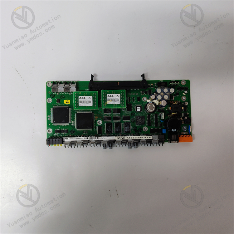
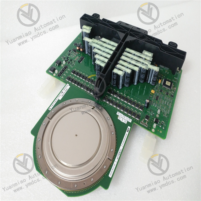
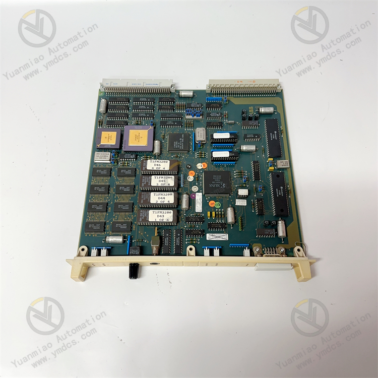
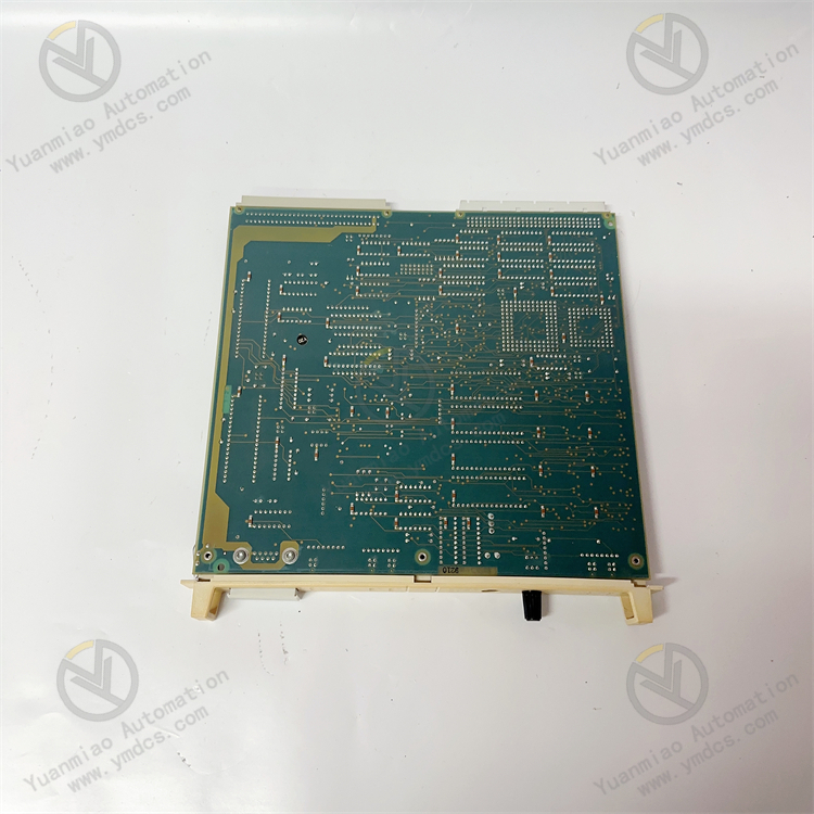
Model: DSCA190V 57310001-PK
Brand: ABB
Product Name: DCS System Bus Communication Processor Module, Fieldbus Communication Card
Product Positioning: ABB DSCA190V 57310001-PK is a high-performance bus communication processor module specially designed for ABB Advant/System 800xA DCS control systems. Serving as the core data exchange hub of the system, it is mainly responsible for data forwarding, protocol parsing, link scheduling and communication fault-tolerant management between controllers, fieldbus devices and upper monitoring systems. Designed for continuous production conditions in process industries such as power generation, chemical engineering, oil & gas and metallurgy, it acts as an original core spare part for DCS system bus networking, signal transmission, equipment capacity expansion and renovation of legacy systems, ensuring stable communication links and accurate & reliable data transmission of the control system.
Core Functions: The module supports adaptive switching of dual bus protocols, compatible with ABB native AFB fieldbus and PROFIBUS DP industrial bus, and coordinates full-system data exchange tasks. It collects field analog and digital process signals in real time and transmits them accurately to the DCS main controller; meanwhile, it forwards control commands from the host computer downwards to realize remote regulation of field equipment. Equipped with functions including link fault self-diagnosis, abnormality isolation, fault alarm and redundant communication protection, it effectively avoids data loss, communication interruption and system data disorder caused by bus interference, transient link breakage and protocol anomalies. It guarantees 24/7 uninterrupted stable operation of the DCS system and improves the real-time performance and reliability of the entire control system. Online firmware upgrade is supported without shutdown or card removal, greatly reducing production losses brought by system maintenance and renovation.
Applicable Systems: Exclusively applicable to ABB Advant Master and full series System 800xA DCS control systems, fully compatible with MasterPiece 200/300 series controllers. It strictly complies with original factory specifications including system bus protocols, rack slot standards, electrical interfaces and installation criteria. Supporting dual-mode bus networking of AFB and PROFIBUS DP, it is suitable for communication module replacement, bus architecture upgrading, station expansion and multi-device networking transformation of legacy DCS systems. New and legacy cards feature excellent interchangeability and compatibility; hot-swap in-situ replacement requires no modification of system control logic and configuration programs with zero adaptation risks.
Application Scenarios: Widely deployed in process industries including thermal power generation, petroleum refining, fine chemical industry, coal chemical industry, metallurgy and water treatment. It applies to fieldbus networking, process data acquisition, remote equipment control and system data exchange of DCS distributed control systems. It can be used for centralized monitoring of production line process parameters, signal transmission of field instruments and actuators, and management of multi-station bus networking, fully adapting to stringent non-stop operating conditions on industrial sites.
2. Technical Features
Adaptive Communication with Dual Protocols, Wide Networking Compatibility Built with an adaptive architecture for dual bus protocols, the module natively supports ABB Advant Fieldbus (AFB) and PROFIBUS DP industrial bus. Communication modes can be flexibly switched according to system networking requirements to adapt to both new and legacy ABB DCS architectures. Under PROFIBUS DP mode, the maximum bus transmission rate reaches 12 Mbps with data transmission delay ≤ 10 ms. Featuring fast response and high real-time performance, it meets data exchange demands of high-precision industrial process control and suits bus networking scenarios with multiple stations, large data volume and strict real-time requirements.
Industrial-grade Redundant Power Supply & Protection, High Operation Stability Adopting industrial dual redundant power input design, it supports wide voltage input of DC 9~36 V, typically matching standard industrial DC24V power supply, effectively resisting on-site voltage fluctuation and transient voltage drop and other power supply anomalies. It integrates DC1500 V electrical isolation, reverse power protection and surge suppression circuits to prevent module damage and communication faults induced by incorrect wiring, voltage impact and electrical interference. The whole unit passes strict EMC electromagnetic compatibility certification, capable of operating in complex environments with strong electromagnetic interference such as power distribution rooms and industrial workshops without parameter drift or communication disorder during long-term operation.
Intelligent Link Self-diagnosis & Fault Alarm, Convenient and Efficient Maintenance Equipped with an on-board integrated intelligent self-diagnosis system and status indicators, it visually displays module power status, bus link status, communication running status and fault alarm status in real time. It monitors faults round-the-clock such as bus disconnection, protocol mismatch, data packet loss, station address conflict and hardware abnormality, and accurately locates fault points and types. It provides independent fault relay output that can connect to the system alarm loop to feed back power supply faults and fiber link faults. Fault logs are automatically stored and support online reading and fault tracing from the host, significantly shortening troubleshooting and maintenance cycles.
Online Non-stop Firmware Upgrade for System Maintenance & Upgrading Remote online firmware upgrade and program update are available via upper communication ports. Firmware iteration, program optimization and protocol adaptation upgrade can be implemented during normal system operation without equipment shutdown or card dismounting. It effectively avoids production losses caused by traditional card upgrade shutdowns, meets demands of system optimization and transformation for continuous industrial production, improves system maintenance efficiency and reduces renovation costs and production outage risks.
Standard DIP Switch Configuration, Flexible Networking Setup The module is fitted with side-mounted DIP switches for manual setting of bus station addresses ranging from 1 to 31, effectively avoiding address conflicts in multi-device networking. It features simple networking configuration and convenient commissioning. It supports independent networking by single module and capacity expansion via parallel connection of multiple modules, flexibly adapting to networking demands from small standalone systems to large plant-wide distributed control systems with strong expandability for various system expansion, renovation and upgrading projects.
- Modular Plug-and-play Design, Strong Interchangeability & Adaptability Designed as a standardized rack-mounted module strictly following ABB original hardware specifications, slot definition, bus communication protocols, electrical parameters and installation standards. Its outline dimensions, mounting positions, pin definitions and communication logic are fully matched with original systems. It supports direct in-situ hot-swap replacement of faulty legacy modules without revising system control logic or reconfiguring the whole system. It covers all scenarios including routine maintenance, fault replacement, system expansion and architecture upgrading with zero compatibility risks.
3. Specification Parameters
| Item | Parameter |
|---|---|
| Model | DSCA190V 57310001-PK |
| Manufacturer | ABB |
| Equipment Type | DCS System Bus Communication Processor Module, Fieldbus Communication Card |
| Applicable Systems | ABB Advant Master, System 800xA DCS System, compatible with MasterPiece 200/300 Series Controllers |
| Application Scope | Bus networking, process data exchange, remote equipment control, system expansion & renovation and legacy equipment replacement for DCS systems in power, chemical, oil & gas and metallurgy industries |
| Core Functions | Adaptive communication of dual bus protocols, bus data transceiving & parsing, station address configuration, link self-diagnosis, fault relay alarm, online firmware upgrade, abnormal data filtering, bus link fault-tolerant management |
| Supported Bus Protocols | ABB Advant Fieldbus (AFB), PROFIBUS DP |
| Bus Transmission Rate | Max. 12 Mbps under PROFIBUS DP mode, data transmission delay ≤ 10 ms |
| Station Address Range | 1~31 (manually set via side DIP switches) |
| Power Supply Specification | Dual redundant power input, wide voltage DC 9~36 V, typical DC24 V |
| Typical Power Consumption | Less than 4 W, low power consumption for stable operation |
| Electrical Protection Level | DC1500 V electrical isolation, reverse power protection, surge suppression, electrostatic discharge protection |
| Alarm Output Contact | Fault relay output, contact rating DC48 V/1 A, supports power fault and fiber link fault alarm |
| Operating Temperature | -20℃ ~ +50℃ (industrial standard wide temperature range) |
| Storage Temperature | -30℃ ~ +85℃ |
| Ambient Humidity | 5% ~ 95% RH, non-condensing, suitable for indoor industrial cabinet environment |
| Protection Performance | Electromagnetic shielding, vibration resistance, dust & moisture resistance, electrical isolation, anti-voltage fluctuation, passed industrial EMC certification |
| Operation Mode | Adaptive bus communication, real-time data transceiving, full-cycle link monitoring, automatic fault alarm, online firmware iteration, abnormal link isolation |
| Upgrade Method | Remote online upgrade via upper port, no shutdown and no card removal required |
| Installation Method | Standard slot mounting in DCS rack, in-situ hot-swap replacement, modular assembly |
| Overall Dimension | 132mm × 105mm × 52mm |
| Equipment Weight | Approx. 0.452 kg |
| Equipment Characteristics | Adaptive dual-protocol communication, redundant wide-voltage power supply, high real-time & low latency, intelligent self-diagnosis and alarm, online non-stop upgrade, strong anti-interference, fully interchangeable with original spare parts, suitable for long-term stable operation of DCS systems |
4. Working Principle
4.1 Power-on Initialization and Full-unit Self-diagnosis
After connected to redundant power supply of the DCS rack, the module automatically completes power-on initialization. It simultaneously launches comprehensive self-inspection of power circuits, bus communication units, fault alarm loops and core arithmetic circuits. It automatically verifies hardware integrity, bus protocol adaptability, validity of DIP address and firmware program, and comprehensively detects potential hazards including abnormal power supply, port faults, address conflicts, program disorder and hardware damage. Once self-test passes, it automatically matches the system bus type (AFB/PROFIBUS DP), completes handshake with DCS controllers and fieldbus devices, and enters normal bus communication operation status.
4.2 Adaptive Dual-protocol Matching and Bus Networking
During operation, the module automatically adapts to corresponding bus protocols according to DCS networking architecture without complicated configuration switching. Under AFB mode, it adapts to ABB native DCS bus architecture to realize internal data exchange between system devices. Under PROFIBUS DP mode, it connects to general industrial bus network to communicate with third-party field instruments, actuators and monitoring equipment. Unique station address is set via side DIP switches to avoid address conflicts in multi-device networking and ensure orderly, stable and interference-free operation of the bus network.
4.3 Bidirectional Data Parsing and High-speed Data Exchange
As the core forwarding unit of the system bus, the module continuously performs bidirectional data exchange tasks. Uplink: collect field analog and digital process signals in real time, conduct data filtering, decoding, verification and preprocessing to eliminate interference clutter and invalid messages, and upload accurate process data to DCS main controllers and upper monitoring systems. Downlink: accurately receive control commands, parameter setting instructions and configuration commands from host computers, parse and distribute them to field actuators to realize precise remote regulation of process equipment. Low-latency, distortion-free and highly synchronous data transmission is maintained throughout the process.
4.4 Full-condition Link Monitoring and Fault Protection & Alarm
The module monitors bus link status, data transmission quality, power supply conditions and hardware operation status round the clock. In response to common on-site faults such as bus interference, transient link breakage, data loss, address conflict, power fluctuation and fiber link abnormality, it rapidly activates adaptive fault-tolerant mechanisms, automatically isolates abnormal links and filters invalid messages. Meanwhile, fault alarm signals are output via on-board indicators and dedicated relays, and fault codes & logs are uploaded to the system background to remind maintenance personnel to conduct timely troubleshooting, preventing fault escalation leading to system communication paralysis and process out-of-control.
4.5 Online Firmware Iteration and System Maintenance Adaptation
The module is equipped with dedicated upper communication ports for remote online firmware upgrade and program optimization under normal system operation. Maintenance engineers can implement firmware update, protocol adaptation upgrade and program bug fixing via upper configuration software without equipment shutdown, card dismounting or production interruption. The upgrade process supports power failure protection and program verification. After upgrade completion, automatic restart adaptation and synchronization of system configuration parameters are carried out to guarantee stable operation and consistent parameters before and after upgrading, satisfying long-term maintenance demands of continuous industrial production.
5. Common Failures and Solutions
5.1 Phenomenon: No operation indicator after power-on, system fails to recognize the card, complete interruption of bus communication
Possible Causes:
① Abnormal dual-channel power supply, voltage out of DC 9~36 V range, loose wiring;
② Oxidation of module gold fingers and accumulated dust in rack slots leading to bus handshake failure;
③ Conflicts or incorrect setting of DIP station addresses with field devices;
④ Damaged firmware, version incompatibility or program crash;
⑤ Aging and damage of core communication hardware of the module.
Solutions:
Shut down the system and discharge residual electricity. Detect voltage and circuit continuity of dual power supply loops, fasten power terminals and eliminate abnormal voltage and loose wiring risks. Take out the module in a dust-free environment, clean oxidized gold fingers and dust in rack slots, then reinsert firmly. Recheck and properly set DIP station addresses to avoid networking address conflicts. Re-flash compatible original firmware and restore default communication parameters and configurations of the module. If the card remains unrecognized after verifying power supply, contact condition, address and firmware, hardware damage is confirmed and original DSCA190V module replacement is required.
5.2 Phenomenon: Frequent bus disconnection, data packet loss, high transmission delay and abnormal data refresh
Possible Causes:
① Damaged bus cables, loose connectors and abnormal line impedance;
② Severe on-site electromagnetic interference and non-standard bus shielding grounding resulting in distorted messages;
③ Mismatched bus protocol selection with system architecture and incorrect configuration parameters;
④ Excessive stations on the bus and overloaded network;
⑤ Degraded communication unit performance and abnormal data processing of the module.
Solutions:
Fully inspect bus cables, connectors and wiring routes, replace damaged cables, fasten terminals and optimize bus shielding grounding to isolate electromagnetic interference. Verify system bus architecture, reselect AFB/PROFIBUS DP protocol and calibrate transmission rate and station parameters. Reduce bus-mounted equipment to avoid overload operation. Monitor bus operation status via system background and reset module communication program. If the fault persists after rectification, communication performance degradation is confirmed and module replacement is needed.
5.3 Phenomenon: Frequent alarm of fault relay indicating power supply / link abnormality
Possible Causes:
① Frequent power voltage fluctuation and excessive transient voltage drop leading to insufficient power stability;
② Poor contact and aging bus cables with intermittent disconnection;
③ Incorrect alarm loop parameters and unreasonable threshold setting;
④ Aging detection circuit of the module resulting in false alarms.
Solutions:
Inspect rack power quality, stabilize voltage and filter ripples to eliminate voltage fluctuation and transient drop risks for stable power supply. Inspect bus links section by section, replace aging cables and fasten terminals to fix intermittent disconnection faults. Log into system background to calibrate alarm thresholds and loop parameters and restore original default settings. Reset module alarm detection program and clear abnormal cache. If false alarms still occur frequently, hardware failure of detection circuit is confirmed and spare module replacement is required.
5.4 Phenomenon: Protocol adaptation failure, unable to connect to target bus network and networking failure
Possible Causes:
① Mismatched module protocol mode with system bus type;
② Incorrect configuration of bus transmission rate, checksum parameters and networking access rights;
③ Outdated firmware of upper controller incompatible with module communication protocol;
④ Abnormal protocol parsing kernel and program malfunction of the module.
Solutions:
Re-select AFB or PROFIBUS DP protocol mode according to on-site DCS architecture. Unify transmission rate, data checksum and session parameters between module and controller, and enable communication access rights. Upgrade upper controller to compatible firmware to ensure hardware & software version matching. Re-download bus configuration program and restart the module to complete networking handshake. If networking still fails after verifying parameters and versions, protocol parsing fault is confirmed and original module replacement is required.
5.5 Phenomenon: Online firmware upgrade failure, upgrade interruption and abnormal program lagging
Possible Causes:
① Unstable communication link during upgrade and data transmission interruption;
② Mismatched firmware version with module hardware model or corrupted firmware file;
③ Abnormal module storage space and program cache overflow;
④ Voltage fluctuation interfering with program writing during upgrade.
Solutions:
Optimize communication environment for stable interference-free link during upgrade to avoid data interruption. Verify hardware model and adopt stable original compatible firmware to eliminate version mismatch. Clear module program cache, release storage space and reset system program. Ensure stable power supply during upgrade to prevent voltage fluctuation disturbing program writing. If upgrade fails repeatedly, hardware fault of storage or program unit is confirmed and module replacement is required.
5.6 Phenomenon: Excessive heat after long-term operation, occasional communication restart and instantaneous data jump
Possible Causes:
① Blocked cabinet air duct and accumulated dust leading to poor heat dissipation and high module temperature;
② Long-term high-load operation of bus network and overloaded data processing of the module;
③ Excessive power ripple and clutter interfering with stable operation;
④ Program redundancy and lagging caused by long-running firmware.
Solutions:
Stop operation, clean cabinet air duct and dust on module surface, optimize ventilation to stabilize cabinet temperature. Reasonably allocate bus station load to avoid continuous high-load operation of the module. Inspect and optimize rack power supply, stabilize voltage and filter clutter interference. Upgrade to stable original firmware and optimize program scheduling logic to reduce unnecessary power consumption. If overheating, communication restart and data jump occur repeatedly, hardware aging is confirmed. Replace the spare module in advance to guarantee long-term stable system operation.