Description
ABB TA528 1SAP181200R0001
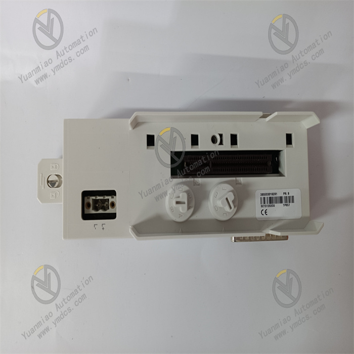
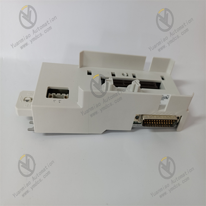
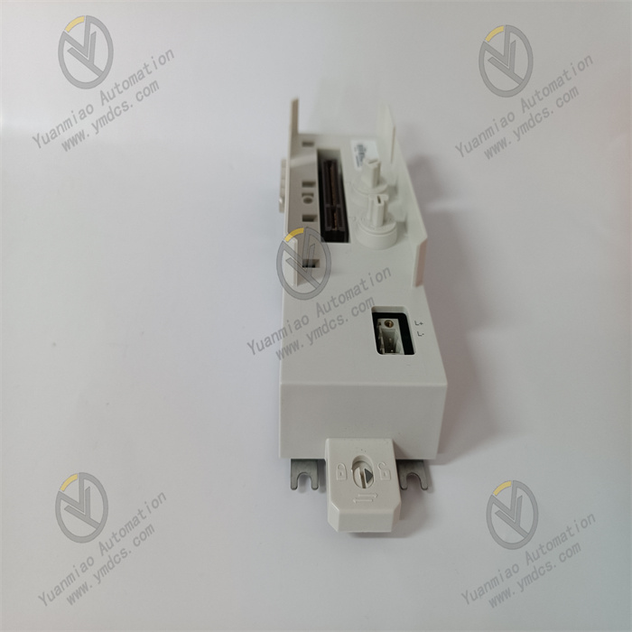
ABB TA528 (1SAP181200R0001) is a 9‑pole spring‑type terminal for the COM1 port of AC500 series PLCs. Designed specifically for the communication interface (COM1) of CPU modules, it enables tool‑free, vibration‑resistant, and reliable communication connections, and is widely used in field communication and upper‑system docking scenarios for all AC500 PLC series.
I. Core Functions & Technical Advantages
1. Core Functions
- 9‑pole fast communication wiring: Standard 9‑pole configuration precisely matches the COM1 interface definition of AC500 CPU modules, supporting serial communication signal transmission (RS232/RS485, etc.). With spring‑crimp structure, it enables plug‑and‑play installation without tools, greatly reducing wiring time for communication cables in control cabinets.
- High‑reliability communication connection: Spring terminals feature low contact resistance, anti‑loosening, and anti‑vibration performance, avoiding communication interruptions caused by on‑site vibration; firm and reusable, eliminating common faults such as screw slippage and poor contact.
- Genuine interface compatibility: Designed and manufactured by ABB, 100% compatible with the COM1 interface of AC500 series CPU modules, avoiding interface mismatches and signal interference from third‑party accessories, ensuring communication stability.
- Bulk supply: Each package contains 5 terminals, meeting the batch wiring needs of multi‑modules in small and medium‑sized projects, reducing procurement and inventory costs.
2. Key Advantages
- Industrial‑grade durability: The housing is made of flame‑retardant engineering plastic with IP20 protection, suitable for installation in control cabinets; operating temperature range is 0~60℃, storage temperature is ‑40~70℃, withstanding temperature fluctuations and dust interference in industrial environments.
- Anti‑interference & safety: Terminals are insulated from the housing; used with shielded cables to effectively suppress electromagnetic interference, ensuring pure communication signals; complies with industrial electrical safety standards, avoiding on‑site electrical safety risks.
- Easy maintenance: Plug‑in structure allows direct insertion and removal without re‑stripping or crimping during module replacement or communication cable adjustment, significantly reducing downtime; modular design does not occupy extra installation space, keeping the cabinet layout neat.
II. Technical Specifications
| Category | Item | Value |
|---|---|---|
| Basic Specs | Model | TA528 (1SAP181200R0001) |
| Product Type | 9‑pole spring‑type terminal for AC500 PLC COM1 port | |
| Package Qty | 5 pcs/pack | |
| Poles | 9 poles (for COM1 interface) | |
| Connection Method | Spring crimp (screwless, plug‑and‑play) | |
| Electrical Specs | Applicable Interface | COM1 communication interface of AC500 CPU module |
| Contact Resistance | Very low, compliant with IEC industrial terminal standards | |
| Insulation Voltage | Meets electrical isolation requirements of PLC communication interfaces | |
| Environ. & Mech. | Operating Temp | 0~60℃ |
| Storage Temp | ‑40~70℃ | |
| Protection Degree | IP20 (must be installed in IP54 or higher control cabinet) | |
| Material | Housing: Flame‑retardant engineering plastic; Terminals: Tin‑plated copper alloy | |
| Weight | Approx. 0.4 kg per pack |
III. Application Areas
- Factory Automation: Communication connections between AC500 PLC COM1 ports and upper computers, HMI, or on‑site equipment in production lines such as automotive manufacturing, electronic processing, and food and beverage.
- Process Industry: Communication bus wiring for AC500 distributed systems in petrochemical, metallurgical, and water treatment scenarios, ensuring stable data transmission.
- Power & Infrastructure: Supporting communication interfaces of AC500 PLCs in power substation auxiliary systems, rail transit, and building automation, realizing remote data upload and instruction distribution to monitoring platforms.
- System Retrofit: Replacing old communication terminals when upgrading old systems to AC500, improving communication reliability and wiring efficiency, and shortening renovation construction period.
IV. Installation & Commissioning Guide
1. Pre‑Installation Preparation
- Model verification: Confirm that TA528 is compatible with the COM1 interface of the used AC500 CPU module (such as PM571, PM581, etc.), check package integrity, and ensure 5 terminals are undamaged and deformed.
- Safety preparation: Cut off the power of the control cabinet and wait for capacitors to discharge for ≥ 5 minutes; wear an anti‑static wristband to avoid damaging electronic components; the installation environment shall be dry, free of condensation and strong electromagnetic interference.
- Tools & wires: Prepare a wire stripper (strip length suitable for terminals, generally 5~7mm), multimeter, cleaning brush; recommend shielded multi‑strand copper wires (0.5~1.5mm²) to ensure communication anti‑interference.
2. Hardware Installation
- Wire preparation: Strip the insulation layer of the wire to the specified length, remove oxidation layer and burrs; do not expose too much copper wire to avoid short circuit.
- Terminal wiring: Press the operating lever of the spring terminal, insert the corresponding communication wire (TX, RX, GND, etc.) vertically to the bottom of the terminal, release the lever for automatic clamping; gently pull the wire to confirm firmness; strictly wire according to the interface definition, do not connect the wrong pins.
- Terminal installation: Align the wired TA528 terminal with the COM1 interface of the AC500 CPU module, push it steadily and lock the buckle; hot plugging is strictly prohibited to avoid damaging the interface chip.
- Inspection: Use a multimeter to detect the continuity and wiring correctness of each pin, confirm no short circuit or virtual connection; check that the terminal housing is undamaged and the buckle is firmly locked.
3. Commissioning & Verification
- Power on the control cabinet, start the AC500 PLC, read the device status through Control Builder Plus software, and confirm no communication fault alarm.
- Connect the upper computer (PC/configuration software), test the communication link: send instructions to read PLC data and remotely control module start/stop to verify accurate data transmission and timely response.
- Perform on‑site vibration simulation (tap the cabinet gently), observe no communication interruption or data packet loss of the PLC, and confirm the anti‑vibration performance of the terminal is good.
V. Common Problems & Solutions
| Common Problem | Troubleshooting & Handling |
|---|---|
| Terminal cannot be inserted into module interface | 1. Confirm that the module model is AC500 series and the interface is COM1; 2. Clean dust/foreign matter in the interface, check if the terminal buckle is deformed; 3. Do not insert violently, push gently in line with the interface. |
| PLC communication abnormal/packet loss | 1. Check if the wiring definitions (TX/RX/GND, etc.) are wrong; 2. Check if the wire diameter is compliant and the stripping length is appropriate; 3. Use a multimeter to detect good terminal contact, replace the terminal if necessary; 4. For RS485, check if the terminal resistance is configured correctly. |
| No communication response | 1. Check if the COM1 port parameter settings (baud rate, parity bit, stop bit) of the PLC are consistent with those of the upper computer; 2. Measure if the terminal power supply (if required) is normal; 3. Troubleshoot if there are strong interference sources nearby, replace with shielded cables and ground reliably if necessary. |
| Terminal housing heating/damage | 1. Check if the operating temperature exceeds 60℃ and optimize the heat dissipation of the control cabinet; 2. Confirm that the terminal is not overloaded, troubleshoot for short circuit faults; 3. If the housing is deformed/damaged, replace with a new terminal immediately. |