Description
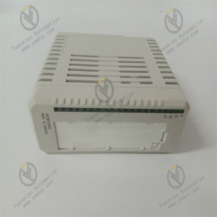
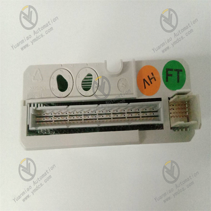
ABB AI890 3BSC690071R1
ABB AI890 3BSC690071R1 is a high-precision analog input module for industrial automation control systems. Its core positioning is to achieve accurate acquisition and stable transmission of various analog signals in industrial sites. It undertakes the core task of converting analog signals generated by converting on-site physical quantities such as temperature, pressure, flow rate, and liquid level into digital signals recognizable by the control system, while ensuring the accuracy of signal acquisition and the reliability of transmission. It is a key interface component connecting on-site industrial sensors/transmitters and the upper control system.
This module is widely used in industrial scenarios with stringent requirements for signal acquisition accuracy and stability, including power energy (thermal power DCS systems, new energy power station monitoring loops), metallurgical manufacturing (smelting process parameter monitoring), petrochemical industry (refining and chemical unit process monitoring), municipal engineering (sewage treatment parameter acquisition), and intelligent manufacturing (production line working condition monitoring).
Adopting an industrial-grade enhanced design and a high-precision signal acquisition circuit, it features high acquisition accuracy, strong anti-interference capability, and flexible channel configuration. It can be accurately matched with mainstream distributed control systems such as ABB AC 800M and Symphony Plus, providing reliable data support for the precise control and working condition monitoring of industrial automation systems.
Relying on high-precision A/D conversion technology, full-channel electrical isolation design, and flexible signal adaptation capability, the ABB AI890 3BSC690071R1 module can flexibly adapt to the signal output requirements of different types of sensors/transmitters. While improving the accuracy and stability of analog signal acquisition, it enhances the adaptability between the control system and on-site monitoring equipment, reduces control deviations and monitoring errors caused by signal acquisition distortion and interference, lowers operation and maintenance costs, and serves as a key core component in industrial automation monitoring and control loops.
1. Product Features
1.1 High-Precision Signal Acquisition with Excellent Conversion Performance
1.2 Full-Channel Electrical Isolation with Strong Anti-Interference Capability
1.3 Flexible Signal Adaptation for Compatibility with Multiple Sensors
1.4 Comprehensive Diagnostic Functions for Accurate Fault Location
1.5 Modular Design for Easy Installation and Configuration
1.6 Wide Working Condition Adaptability with Excellent Environmental Suitability
2. Technical Parameters
2.1 Basic Parameters
- Model: ABB AI890 3BSC690071R1
- Product Type: Analog Input Module
- Brand: ABB
- Product Series: AC 800M/Symphony Plus Control System I/O Module Series
- Application Fields: Power energy (thermal power DCS system, new energy power station monitoring loop), metallurgical manufacturing (smelting process parameter monitoring), petrochemical industry (refining and chemical unit process monitoring), municipal engineering (sewage treatment parameter acquisition), intelligent manufacturing (production line working condition monitoring)
- Compatible Systems: ABB AC 800M Controller, ABB Symphony Plus Control System
- Number of Input Channels: 8 channels (each channel can be independently configured)
- Mounting Method: Rail Mounting/Backplane Bus Plug-in Mounting
- Net Weight: Approximately 0.52kg
- Warranty Period: 12 months
- RoHS Compliance: Complies with EU Directive 2011/65/EU (RoHS 2.0)
- WEEE Category: Category 5 (small electronic equipment)
2.2 Electrical Parameters
- Supply Voltage: 24V DC±10%
- Power Consumption: Typical value ≤7W (full load operation), maximum value ≤10W
- Input Signal Types: Thermocouples (J, K, S, R, T, B, E, N types), thermal resistors (Pt100, Pt1000, Cu50, Cu100), 4-20mA DC current signals, 0-10V DC voltage signals (each channel can be independently configured)
- A/D Conversion Accuracy: 24-bit
- Acquisition Accuracy: ±0.01% FS
- Linearity: ≤±0.005% FS
- Sampling Rate: Up to 100Hz per channel (configurable)
- Filtering Time: 0.1ms~10s adjustable
- Isolation Level: Mutual isolation between channels, full isolation between channels and power supply/backplane bus, rated isolation voltage 250V AC (continuous)
- Protection Functions: Overvoltage protection, short-circuit protection, ESD protection (±2kV contact discharge, ±8kV air discharge), surge protection (±2kV at power supply terminal, ±1kV at signal terminal)
- Communication Interface: Backplane bus interface (compatible with ABB AC 800M bus protocol)
- Sensor Power Supply: Some channels can provide 24V DC excitation power supply, with a maximum output current of 200mA per channel
2.3 Mechanical and Environmental Parameters
- Dimensions (W×H×D): 48mm×130mm×115mm
- Operating Temperature: -25℃~+70℃
- Storage Temperature: -40℃~+85℃
- Relative Humidity: 5%~95%RH (no condensation)
- Electromagnetic Interference Resistance: Complies with EN 55011 Group 1 Class A, EN 61000-4-2 (ESD), EN 61000-4-3 (radiated immunity), EN 61000-4-4 (electrical fast transient), EN 61000-4-5 (surge) standards
- Vibration Resistance: Complies with IEC 60068-2-6 standard, 10-150Hz, acceleration 5g
- Impact Resistance: Complies with IEC 60068-2-27 standard, acceleration 15g, duration 11ms
- Protection Rating: IP20 (front-end protection after installation)
- Housing Material: Flame-retardant engineering plastic + metal shielding cover
3. Working Principle
The core working logic of the ABB AI890 3BSC690071R1 analog input module is "Power Supply - Signal Acquisition - Signal Conditioning - A/D Conversion - Digital Signal Transmission - Status Monitoring - Fault Feedback". The specific working process is as follows:
4. Common Fault Troubleshooting
| Fault Phenomenon | Possible Causes | Troubleshooting and Solutions |
|---|---|---|
| No response when the module is powered on, and the status indicator light does not turn on | Abnormal power supply (power failure, voltage out of the range of 24V DC±10%), loose connection of power terminals/backplane bus, damaged power connection cable, internal power circuit failure of the module | Use a multimeter to measure the voltage of the power supply terminals to confirm that the voltage meets the requirement of 24V DC±10%; check whether the wiring of the power terminals or the connection of the backplane bus is firm, re-plug or tighten the connection; check whether the power connection cable is damaged or broken, and replace it with a high-quality power connection cable; if the above inspections are all normal but there is still no response, there may be a fault in the internal power circuit of the module, and it is necessary to contact ABB authorized after-sales service for maintenance or module replacement. |
| Abnormal data collected by a certain channel (overrange, large fluctuation), other channels are normal | Channel configuration error (mismatched signal type and measurement range), sensor/transmitter failure, damaged or loosely connected signal cable, channel short circuit/open circuit, abnormal sensor power supply | Check the configuration of the channel through the control system software to confirm that the signal type and measurement range match the sensor/transmitter, reconfigure and save; disconnect the connection between the channel and the sensor, connect a standard signal source to the channel for testing; if the data is normal, the fault lies in the sensor/transmitter, and it needs to be replaced; check whether the signal cable connection is firm, and replace the damaged cable; if it is a thermal resistance/thermocouple channel, check whether the sensor wiring is correct and confirm that the cold-junction compensation is normal; if the sensor requires power supply, measure whether the excitation power output of the module is normal. |
| Data collected by all channels fluctuates greatly with large accuracy deviation | Poor grounding of the module, excessive electromagnetic interference in the installation environment, unshielded signal cables or ungrounded shielding layers, excessively short configured filtering time, uncalibrated module or lost calibration parameters | Check whether the module grounding is reliable, re-tighten the grounding terminal to ensure that the grounding resistance meets the requirements; replace with twisted-pair shielded cables for signal transmission to ensure that the shielding layer is grounded at one end (control system end); check whether the module installation location is close to strong interference sources, install a metal shielding cover or optimize the line layout; appropriately increase the channel filtering time parameters to improve signal stability; calibrate the accuracy of the module through the control system software and re-save the calibration parameters. |
| The module frequently triggers channel fault alarms | Incorrect channel wiring, damaged insulation layer of the signal cable leading to short circuit, sensor disconnection, excessively low configured fault threshold, internal channel circuit failure of the module | Verify the channel wiring method to ensure that it matches the type of sensor/transmitter (e.g., correct polarity of thermocouples, correct three-wire/four-wire wiring of thermal resistors); check whether the insulation layer of the signal cable is damaged and replace it with an intact cable; confirm that the sensor connection is normal without disconnection; re-verify the fault threshold configuration and adjust it reasonably according to the actual on-site requirements; if the above measures are ineffective, there may be a fault in the internal channel circuit of the module, and contact after-sales service for maintenance or module replacement. |
| Communication abnormality between the module and the control system, unable to upload collected data | Loose backplane bus connection, incorrect module address configuration, mismatched communication protocol, outdated module firmware version, control system interface failure | Re-plug the module to ensure that the backplane bus connection is firm; check the module address configuration to ensure that it is consistent with the address allocation in the control system; confirm that the communication protocol configuration is correct and compatible with the control system; check the module firmware version; if the version is outdated, contact ABB authorized after-sales service for firmware upgrade; if other modules communicate normally, there may be a fault in the module communication interface, and contact after-sales service for maintenance or module replacement. |