Description
ABB PM150V08 3BSE009598R1
I. Product Overview
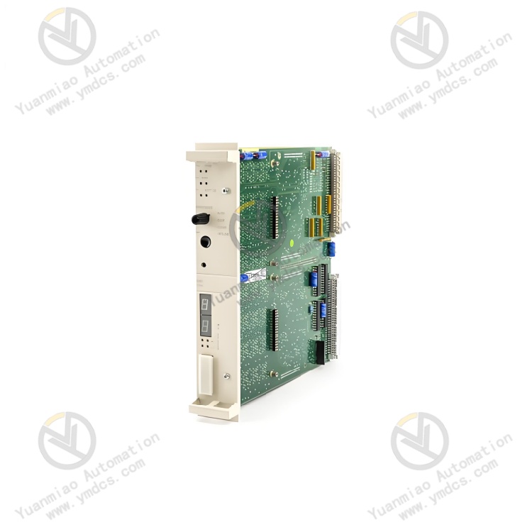
ABB PM150V08 3BSE009598R1 is a compact process control unit specially designed for small and medium - sized industrial automation scenarios. It integrates logic control, process regulation, data acquisition, and multi - protocol communication. Its core functions include analog/digital signal processing, complex logic operations, equipment collaborative control, and cross - system data interaction. Through mainstream industrial protocols such as Modbus and Profinet, it achieves seamless integration with on - site sensors, actuators, upper - level monitoring systems, and third - party equipment. It provides efficient and reliable lightweight control solutions for fields like process industry, intelligent manufacturing, water treatment, building automation, and small - scale chemical plants.
This control unit adopts a modular and compact design, boasting both high - performance computing capabilities and flexible expansion characteristics. Equipped with industrial - grade stable components and multiple protection mechanisms, it supports convenient DIN rail installation and hot - swap maintenance. With its small size, low power consumption, and adaptability to harsh environments, it has become a core control hub connecting underlying equipment and upper - level systems in small and medium - sized industrial scenarios, ensuring the stable and efficient operation of production processes.
II. Functional Features
Compact Size with High - performance Computing and Control Capabilities
Full Signal Compatibility and Data Acquisition Capabilities
Multi - protocol Communication and Seamless Cross - system Integration
Flexible Expansion and Easy Maintenance Design
High Reliability and Multiple Protection Mechanisms
III. Technical Parameters
| Categories | Specific Parameters |
|---|---|
| Product Type | Compact process control unit of the ABB Compact Product Line |
| Core Functions | Logic control, process regulation, data acquisition, signal processing, multi - protocol communication, fault self - diagnosis |
| Processor and Storage | 32 - bit industrial - grade microprocessor with a main frequency of 800MHz; 512KB RAM; 4MB Flash storage |
| Control Performance | Supports up to 1000 function blocks and 80 control loops; Control cycle: 1ms - 10s (configurable); Logic operation response time ≤ 0.1ms per 1000 steps; Regulation accuracy ± 0.02% |
| I/O Channel Configuration | Analog Input (AI): 8 channels (4 - 20mA/0 - 10V, differential input); Digital Input (DI): 8 channels (24VDC, response time ≤ 1ms); Analog Output (AO): 4 channels (4 - 20mA/0 - 10V, accuracy ± 0.1%); Digital Output (DO): 4 channels (24VDC, maximum load of 5A) |
| Programming Methods | IEC 61131 - 3 (LD, FBD, ST, IL, SFC); Supports ABB Control Builder Basic software |
| Communication Protocols | Modbus RTU/TCP, Profinet IO, EtherNet/IP, RS485; Supports OPC UA client/server |
| Communication Interfaces | 2 Ethernet ports (10/100Mbps); 1 RS485 interface (supports half - duplex, baud rate of 9600 - 115200bps) |
| Expansion Capability | Supports modular expansion, with a maximum expandability of up to 32 I/O channels (compatible with ABB Compact series expansion modules) |
| Power Supply Parameters | Supply voltage: 24VDC (±10%); Power consumption: 12W (typical), 18W (maximum) |
| Physical Parameters | Dimensions: 100×80×60mm; Weight: approximately 350g; Installation method: DIN rail mounting (35mm standard DIN rail) |
| Environmental Adaptability | Operating temperature: -20℃ - +60℃; Storage temperature: -40℃ - +85℃; Humidity: 5% - 95% (no condensation); Protection class: IP20; Electromagnetic interference resistance complies with IEC 61000 - 4 |
| Protection Functions | Overcurrent, overvoltage, short - circuit, overheating, and undervoltage protection; Hardware watchdog; Software fault - tolerance mechanism |
| Compatible Systems | ABB Compact series I/O modules; Third - party Modbus/Profinet devices; SCADA/HMI systems; MES/ERP systems |
| Application Scenarios | Small and medium - sized process industry, intelligent manufacturing, water treatment, building automation, small - scale chemical plants, food and beverage production lines, small - scale power equipment control |
IV. Working Principle
Data Acquisition: It receives analog/digital signals (such as temperature, pressure, and equipment operating status signals) from on - site sensors through built - in I/O channels, or receives operating data from third - party equipment via Modbus/Profinet protocols. The collected signals undergo preprocessing such as filtering, scaling conversion, and linearization correction to ensure data accuracy.
- Logic Operation: The 32 - bit microprocessor performs logic judgment and control algorithm operations (such as PID regulation and sequential control) on the collected data in accordance with the preset control program (programmed based on IEC 61131 - 3). It generates control instructions and status feedback information by combining equipment interlocking rules and control thresholds.
Control Output: The computed control instructions are transmitted to actuators (valves, motors, control valves, etc.) through analog/digital output channels, realizing operations such as equipment start - stop and precise parameter regulation. Meanwhile, the operating status of the equipment and control results are fed back to the local LED indicators and LCD screen.
- Communication Interaction: It conducts data interaction with upper - level monitoring systems and third - party equipment through Ethernet/RS485 interfaces. It uploads collected data, operating status, and fault information, and receives remote control instructions and parameter configurations, enabling cross - equipment collaborative control and remote operation and maintenance.
- Fault Diagnosis: It continuously monitors key statuses such as power supply voltage, I/O channel signals, communication links, and module temperature. When abnormalities like overcurrent, overvoltage, short circuits, or communication interruptions are detected, it immediately triggers protective mechanisms (cutting off output and activating fault indicator alarms) and uploads fault codes to facilitate rapid troubleshooting.
V. Operation Guide
1. Installation Steps
Installation Environment: Install it on a 35mm standard DIN rail, away from strong electromagnetic interference sources such as frequency converters and high - voltage cables. Reserve a heat dissipation gap of no less than 10mm on both sides. The control cabinet should be well - ventilated to prevent the ambient temperature from exceeding the range of -20℃ to +60℃, which could lead to reduced module performance due to overheating.
- Mechanical Installation
- Confirm that the main power supply of the control cabinet is cut off. Align the module's buckle with the DIN rail and press until the buckle locks securely to ensure the module is firmly installed without looseness. When multiple modules are installed side by side, maintain a spacing of no less than 5mm to avoid poor heat dissipation or wiring interference.
- If expansion modules are configured, connect them in the order of "main control unit → expansion modules". Use dedicated bus interfaces for connection and tighten the fixing screws to ensure smooth communication links between modules.
Wiring Specifications
- Power Wiring: Connect to a 24VDC power supply, strictly distinguish between positive and negative polarities, and fasten the wiring terminals. It is recommended to connect a 2A fuse in series on the input side. Use 1.0mm² copper core cables for the power lines, with a length not exceeding 8 meters to ensure stable power supply.
- I/O Wiring: Connect the analog input/output channels to sensors/actuators following the "positive - to - positive, negative - to - negative" rule, and ground the shielding layer at one end (ground resistance ≤ 4Ω). Wire the digital input/output channels in accordance with the markings in the equipment manual to avoid short circuits or reversed polarities.
- Communication Wiring: Connect the Ethernet port to the industrial switch using Cat5e/Cat6 shielded network cables, which supports Profinet redundancy configuration. Connect the RS485 interface to the bus following the "A - to - A, B - to - B" rule, and ground the shielding layer at one end. Route communication cables separately from power cables with a spacing of no less than 15cm to reduce electromagnetic interference.
- Notes: Before wiring, confirm that the power supply voltage matches the rated voltage of the module, and never reverse the polarities. When wiring the I/O channels, avoid exceeding the rated current/voltage range to prevent damage to the channels. The communication parameters (baud rate, station number, and IP address) must be consistent with those of the upper - level system.
2. Configuration and Debugging
- Parameter Configuration
- Install the ABB Control Builder Basic programming software and establish a connection with the control unit via Ethernet or RS485 interfaces. Create a new project, select the model PM150V08 3BSE009598R1, and configure basic settings such as communication protocols (e.g., Modbus slave address, Profinet station number, and IP address), I/O channel types, control cycles, and PID parameters.
- Programming and Logic Configuration: Write control logic using IEC 61131 - 3 standard programming methods. Define I/O channel addresses, equipment interlocking rules, control thresholds, and fault response strategies. Support offline simulation tests of the control logic and download it to the control unit after verifying its correctness.
Power - on Debugging
- Before powering on for the first time, verify the correctness of the wiring and the consistency between the module model and configuration parameters. Use a multimeter to check the input power supply voltage (24VDC ± 10%) and ensure there are no short circuits or reversed polarities.
- After powering on, observe the status of the front panel. A steady power indicator (PWR) and a blinking operation indicator (RUN) indicate normal operation. If the fault indicator (FAULT) stays on or the LCD displays a fault code, use the software to read the fault information (such as overcurrent or communication failure) and troubleshoot the wiring or configuration issues.
- Function Testing: Simulate standard sensor input signals (e.g., 4 - 20mA current signals) to verify the accuracy of data acquisition. Force the output of control instructions and observe whether the actuator actions meet expectations. Test the PID regulation function by inputting step signals to verify the regulation accuracy and response time. Simulate equipment faults to verify the effectiveness of the fault self - diagnosis and protection mechanisms.
- Communication Testing: Verify the communication connection between the control unit and the upper - level monitoring system as well as third - party Modbus/Profinet devices to ensure no data loss during transmission and a delay of ≤ 100ms. Test the functions of remote parameter modification, program downloading, and firmware upgrading to confirm the normal operation of remote maintenance.
3. Operation and Maintenance
- Status Monitoring: Real - time monitoring of the operating status can be carried out through the upper - level monitoring system or the local LED indicators/LCD screen:
- Normal Status: Stable power supply, blinking operation indicator, no fault alarms, stable control parameters, and unobstructed communication links.
- Fault Status: The fault indicator stays on, and the LCD displays fault codes (such as overcurrent, communication interruption, or I/O channel failure). Troubleshooting should be conducted by combining the software fault logs and wiring status.
Regular Maintenance
- Monthly: Clean the dust on the module surface and interfaces with dry compressed air. Check the installation firmness and whether the wiring terminals are loose or oxidized. View the operation logs and fault records through the software to analyze potential problems. Inspect the stability of the communication links and power supply.
- Every 6 Months: Conduct a comprehensive inspection to check if the insulation layers of the power cables, communication cables, and I/O wires are damaged or aging, and verify the reliability of the shielding layer grounding. Back up the control programs and configuration parameters (both offline and cloud backups). Test the effectiveness of the fault self - diagnosis and protection functions.
- Annually: Check the internal components of the module for signs of aging (such as swollen capacitors or loose interfaces). Upgrade the programming software and module firmware to the latest stable versions (back up the programs before upgrading). Calibrate the accuracy of the analog input/output channels to ensure control reliability.