Description
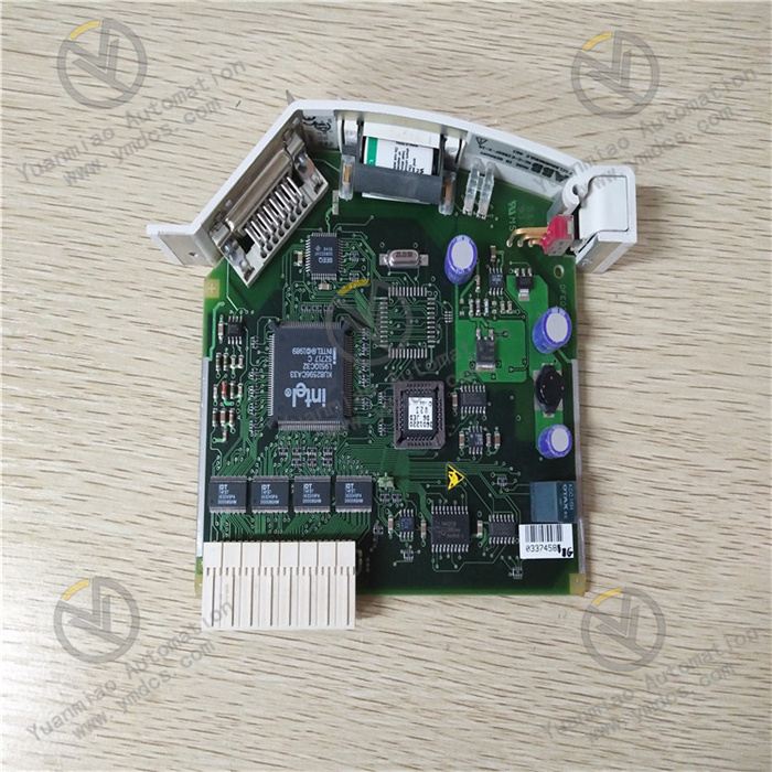
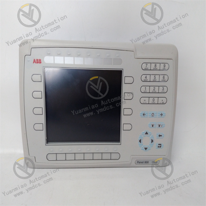
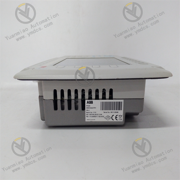
ABB PP836 3BSE042237R1
I. Product Overview
ABB PP836 3BSE042237R1 is an operator panel belonging to the human-machine interaction series of the Advant OCS/AC800M control system. Designed specifically for equipment status monitoring, parameter setting, operation command issuance, and fault alarm handling in industrial automation scenarios, it can be seamlessly integrated into ABB AC800M DCS systems, PLC systems, and third-party compatible control platforms, serving as a core interactive terminal between operators and industrial control systems.
II. Functional Features
High-Definition and Intuitive Human-Machine Interaction Experience
- Equipped with a 15-inch TFT color touch screen with a resolution of 1024×768 pixels, supporting 16.7 million true-color display for clear and delicate images. It adopts industrial-grade resistive touch technology (capacitive touch is optional for some models) with a touch response time ≤ 20ms, supporting multi-touch (optional). The operation is accurate and smooth, suitable for glove-wearing operation scenarios in industrial sites.
- Supports customized interface layout. Multi-page monitoring interfaces can be designed via ABB Panel Builder 600 programming software, including elements such as real-time data display, trend curves, alarm lists, operation buttons, and process flow diagrams, meeting the visualization requirements of different industrial scenarios.
- Built-in high-brightness backlight module with adjustable brightness (200~500cd/m²), featuring anti-glare and anti-reflection treatment for clear display under strong light or dim environments. The screen has a service life of ≥ 50,000 hours, meeting the requirements of long-term continuous operation.
Rich Communication Interfaces and Wide Compatibility
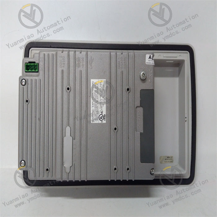
- Integrates multiple types of industrial communication interfaces: 1×Gigabit Ethernet (RJ45), 2×Fast Ethernet (RJ45), 2×RS232/RS485 (configurable), 1×USB 2.0 Host, 1×USB 2.0 Device, and 1×SD card slot. It supports various industrial communication protocols: Profinet, Modbus TCP/RTU, OPC UA/DA, EtherNet/IP, Profibus-DP, etc.
- Can seamlessly connect to ABB AC800M and AC500 series controllers, and is compatible with third-party PLC and DCS systems such as Siemens, Rockwell, and Schneider. It supports data interaction with monitoring systems (SCADA) and MES systems, realizing multi-level industrial network integration.
- Supports network redundancy function; Ethernet interfaces can be configured as redundant connections to ensure the continuity and reliability of data transmission. It supports remote monitoring and maintenance, enabling interface updates, parameter modifications, and fault diagnosis via the network, reducing on-site operation and maintenance costs.
Industrial-Grade Stable Performance and Robust Design
- Adopts an industrial-grade ARM Cortex-A9 processor (main frequency ≥ 1GHz), paired with 512MB DDR3 memory and 4GB Flash storage (expandable to 32GB via SD card). It has powerful data processing capability and storage capacity, supporting multi-task parallel operation with smooth interface switching without lag.
- The body features an IP65 protection rating design; the front panel is waterproof, dustproof, and oil-resistant, capable of withstanding harsh environments in industrial sites. The shell is made of high-strength aluminum alloy material with a vibration resistance of 2g (10-500Hz) and an impact resistance of 10g (11ms), adapting to vibration and impact environments in factory workshops.
- Fanless heat dissipation design with a wide operating temperature range (0℃~+50℃) and storage temperature range (-20℃~+60℃). It can adapt to a relative humidity of 5%-95% (non-condensing), with a mean time between failures (MTBF) of ≥ 80,000 hours, meeting the 24/7 continuous operation requirements of industrial systems.
Safe and Reliable Operation and Fault Handling
- Supports hierarchical operation permission management, allowing the setting of multiple permission levels such as administrator, operator, and observer. Users of different levels have different operation permissions (e.g., parameter modification, start-stop control, interface viewing), preventing system faults caused by misoperation.
- Equipped with real-time alarm function, supporting sound and light alarms (built-in buzzer and alarm indicator). It can display information such as alarm time, alarm type, alarm location, and handling suggestions. Alarm records can store ≥ 10,000 entries, supporting historical alarm query and export for convenient fault tracing and analysis.
- Built-in hardware watchdog and software self-diagnosis function, which can real-time monitor the system operation status (power supply, memory, communication interface). In case of abnormalities, it will automatically restart and recover, and record fault information at the same time to ensure stable system operation. It supports data backup and recovery function; configuration files and historical data can be backed up via USB or SD card to prevent data loss.
Convenient Installation and Flexible Expansion
- Supports two installation methods: panel mounting and wall mounting, with a standardized installation hole size (350mm×260mm) and a weight of approximately 4.5kg, suitable for installation on industrial control cabinet panels or independent on-site installation scenarios. The installation method is simple and fast without complex tools, reducing installation workload.
- Supports functional module expansion; serial port modules, wireless communication modules (Wi-Fi, 4G/5G), printer interfaces, etc., can be expanded through reserved interfaces to adapt to the functional requirements of different industrial scenarios. It supports external device connection; mice, keyboards, and printers can be connected via USB interfaces for convenient data input and report printing.
III. Technical Parameters
| Category | Specific Parameters |
|---|---|
| Product Type | High-performance Industrial Operator Panel (Advant OCS/AC800M Series) |
| Part Number | 3BSE042237R1 |
| Model Designation | PP836 |
| Core Functions | Equipment monitoring, parameter configuration, operation control, alarm handling, data recording and visualization |
| Display Characteristics | Screen size: 15-inch TFT color touch screen; Resolution: 1024×768 pixels; Color: 16.7M true color; Touch type: Resistive (capacitive optional); Response time ≤ 20ms; Brightness: 200~500cd/m² (adjustable) |
| Hardware Configuration | Processor: ARM Cortex-A9 (main frequency ≥ 1GHz); Memory: 512MB DDR3; Storage: 4GB Flash (expandable to 32GB via SD card); Watchdog: Hardware watchdog (1~255 seconds adjustable) |
| Communication Interfaces | Ethernet: 1×Gigabit Ethernet (RJ45), 2×Fast Ethernet (RJ45); Serial port: 2×RS232/RS485 (configurable); USB: 1×USB 2.0 Host, 1×USB 2.0 Device; Expansion interface: SD card slot (supports SDHC) |
| Supported Protocols | Profinet, Modbus TCP/RTU, OPC UA/DA, EtherNet/IP, Profibus-DP, ABB Control Network, etc. |
| Power Supply Parameters | Input voltage: 24VDC (±10%); Power consumption: Typical 25W, Max 35W; Power protection: Overvoltage, overcurrent, reverse connection protection |
| Environmental Adaptability | Operating temperature: 0℃~+50℃; Storage temperature: -20℃~+60℃; Humidity: 5%-95% (non-condensing); Vibration resistance: 2g (10-500Hz); Impact resistance: 10g (11ms) |
| Protection Performance | Protection rating: IP65 (front panel); Electromagnetic compatibility: Complies with IEC 61000-4 standard; Certifications: CE, UL, CSA, ATEX (optional explosion-proof certification) |
| Physical Parameters | Dimensions (W×H×D): 380mm×290mm×55mm; Installation hole size: 350mm×260mm; Weight: Approx. 4.5kg; Installation method: Panel mounting, wall mounting |
| Software Compatibility | Programming software: ABB Panel Builder 600; Supported functions: Custom interface, trend curve, alarm management, permission management, data recording and export |
| Service Life | Screen life ≥ 50,000 hours; MTBF ≥ 80,000 hours (at 25℃) |
| Application Scenarios | Petrochemical engineering, power systems, metallurgical industry, intelligent manufacturing, water treatment, rail transit, energy management, standalone automation |
IV. Working Principle
- Data Interaction: Establish connection with on-site controllers (DCS/PLC) via communication interfaces such as Ethernet and serial ports, real-time receive equipment operation data (e.g., temperature, pressure, flow rate, equipment status) and fault alarm information uploaded by the controller, and simultaneously receive operation instructions (e.g., parameter modification, equipment start-stop) input by operators via the touch screen.
Processing & Analysis: The industrial-grade processor parses, calculates, and processes the received raw data, converts equipment status data into visual charts (e.g., numbers, indicator lights, trend curves), classifies and organizes fault information into alarm lists, and performs permission verification and format conversion on the instructions input by operators to ensure instruction compliance.
- Visual Presentation: Present the processed data in the form of customized interfaces via the 15-inch high-resolution touch screen, including real-time data display area, process flow diagram, trend curve area, alarm prompt area, operation button area, etc., allowing operators to intuitively grasp the equipment operation status.
- Operation Response: When operators perform operations via the touch screen, the device confirms the instructions and then issues the instructions to the controller via communication interfaces, and simultaneously feeds back the operation results on the interface (e.g., operation success prompt, parameter update display).
- Data Feedback: After the controller executes the instructions, it real-time transmits the updated equipment status data back to the operator panel, which synchronously updates the interface display to form closed-loop control, ensuring that operators can timely obtain the operation effect.
V. Operation Guide
1. Installation Steps
Installation Environment
Mechanical Installation
- Confirm that the equipment model (PP836) and part number (3BSE042237R1) meet the design requirements. Check that the equipment has no appearance damage, the screen has no scratches, and the interfaces are not loose. Drill holes on the control cabinet panel or mounting plate according to the standardized installation hole size (350mm×260mm); the edges of the holes should be smooth without burrs.
- Embed the equipment into the holes and lock it from the inner side of the panel with supporting fixing clips to ensure the equipment is installed firmly without loosening. For wall mounting, use a dedicated wall-mounted bracket with a load-bearing capacity ≥ 10kg to ensure stable installation.
Wiring Operation
- Turn off the main power supply of the control cabinet, and connect the power cable and communication cable according to the wiring diagram: the power cable should distinguish between positive and negative poles (24VDC positive pole connected to "+", negative pole connected to "-"); the communication cable should be connected to the controller or network switch according to the interface type (Ethernet, serial port).
- It is recommended to use copper-core cables with a cross-section ≥ 1.5mm² for power cables, with a length not exceeding 5 meters. Use Cat5e or Cat6 shielded cables for Ethernet cables, with the shield layer grounded at one end (ground resistance ≤ 4Ω). Wire the serial cable according to the requirements of the communication protocol (e.g., RS485 needs to distinguish between A, B, and GND). All cables should be fixed firmly to avoid interface loosening caused by pulling.
2. System Configuration
Initialization Settings
- Power on the equipment, which will start automatically (start-up time ≤ 60 seconds) and enter the initial setting interface to configure basic parameters such as system language (supports multiple languages including Chinese and English), date and time, screen brightness, and touch calibration.
- Configure communication parameters: Enter the communication setting interface via panel operation, select the communication interface (Ethernet/serial port), set the IP address, subnet mask, gateway (Ethernet) or baud rate, data bits, parity bits, stop bits (serial port), select the communication protocol (e.g., Modbus TCP, Profinet), and establish communication connection with the controller.
Interface Deployment
- Install ABB Panel Builder 600 programming software on a PC, design monitoring interfaces according to the requirements of industrial scenarios, add elements such as data display controls, operation buttons, trend curves, alarm lists, and process flow diagrams, associate controller register addresses, and set data formats and display methods.
- Upload the designed interface program to the operator panel via USB interface or network; the program will run automatically after the equipment is restarted. Test the interface functions: check whether the data display is real-time and accurate, whether the operation buttons respond normally, whether the trend curves update smoothly, and whether the alarm function is effective.
Permission Configuration
- Set user permission levels in Panel Builder 600 software, add user accounts and passwords (supports ≥ 100 users), and assign operation permissions to users of different levels (e.g., administrators can modify all parameters, operators can only perform start-stop operations, and observers can only view data).
- Upload the permission configuration file to the equipment and enable the permission management function to ensure operation safety. Update user passwords regularly to avoid permission leakage.
3. Operation and Maintenance
Daily Operation
- After logging in with their accounts, operators can view real-time equipment operation data, trend curves, and alarm information via the touch screen, and perform operations such as parameter modification and equipment start-stop. Operators should confirm that the instructions are correct before operation to avoid misoperation.
- Check the alarm list regularly, handle fault alarms in a timely manner, and confirm alarm reset on the panel after handling. Export historical alarm records and data reports regularly to facilitate equipment maintenance and process optimization.
Regular Maintenance
- Weekly: Wipe the screen surface and equipment shell with a dry soft cloth to remove dust and oil stains (avoid using corrosive cleaning agents such as alcohol and acetone). Check whether the cable connections are firm and whether the interfaces have signs of loosening or oxidation.
- Monthly: Check whether the power supply voltage is stable (24VDC±10%). Test the touch calibration accuracy; recalibrate if touch offset occurs. Back up configuration files and historical data to a USB or SD card. View the system log to troubleshoot potential faults.
- Annually: Conduct a comprehensive inspection of the equipment, checking the screen display effect, key response speed, and communication stability. Test the hardware watchdog function and simulate faults to verify the automatic restart and recovery function. Check the equipment heat dissipation to ensure the fanless heat dissipation works normally. Contact after-sales service for professional inspection and maintenance if necessary.
4. Common Fault Troubleshooting
| Fault Phenomenon | Possible Causes | Troubleshooting Methods |
|---|---|---|
| The equipment cannot start with no display | Power supply fault, incorrect power wiring, equipment fault | Check whether the power supply voltage is 24VDC±10%; verify the positive and negative pole wiring of the power supply; test with a backup power supply; if there is still no response, contact after-sales service to inspect the equipment |
| No touch response/touch offset on the screen | Invalid touch calibration, oil stains/scratches on the screen surface, touch panel fault | Wipe the screen with a clean soft cloth; perform touch calibration in the system settings; if there is still no response, check whether the touch panel is damaged and contact after-sales service for repair |
| Cannot establish communication with the controller | Incorrect communication parameter configuration, communication cable fault, controller fault | Verify communication parameters such as IP address and baud rate; test with a replacement communication cable; check whether the controller communication interface is normal; perform a ping test to check network connectivity |
| Abnormal data display/no refresh | Communication interruption, incorrect register address association, abnormal controller data | Check the communication connection status; verify the association between interface controls and controller register addresses; check whether the controller outputs data normally; restart the equipment and the controller |
| Invalid alarm function | Incorrect alarm parameter configuration, buzzer/indicator light fault, controller not sending alarm signals | Check the alarm threshold and alarm trigger condition configuration; test whether the buzzer and indicator light work normally; check the controller alarm signal output; re-upload the alarm configuration file |
| Lagging interface switching/crash | Insufficient memory, program exception, hardware fault | Close redundant programs to free up memory; restore factory settings and re-upload the interface program; check whether the hardware temperature is too high; if frequent crashes occur, contact after-sales service for inspection |
| USB/SD card not recognized | Device compatibility issues, interface fault, storage medium damage | Test with a compatible USB/SD card; check whether the interface is loose or oxidized; reformat the storage medium and try again; if it is still not recognized, inspect the interface hardware |