Description
ABB AI620 3BHT300005R1
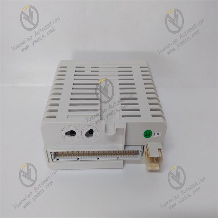
ABB AI815 3BSE052604R1 is an analog input module belonging to the Advant OCS/AC800M control system expansion module series. Designed specifically for multi-channel analog signal acquisition, conditioning, and transmission in industrial automation scenarios, it can be seamlessly integrated into the ABB AC800M DCS system and compatible control platforms, serving as a key signal connection component between field sensors and controllers.
Featuring an 8-channel differential input structure, this product supports a variety of industrial standard analog signal types. It boasts stable measurement performance, reliable anti-interference design, and modular installation characteristics. Strictly complying with industrial standards such as IEC 61158 and IEC 61000, it has obtained authoritative certifications including CE and UL. Widely applied in scenarios such as petrochemical engineering, power systems, metallurgical industry, intelligent manufacturing production lines, and water treatment processes, it is responsible for collecting analog signals output by sensors for temperature, pressure, flow rate, liquid level, etc., providing accurate and continuous raw data support for control systems. It has the advantages of strong compatibility, high reliability, convenient installation and maintenance, and outstanding cost-effectiveness.
Equipped with 8 independent differential input channels, it supports multiple types of industrial standard analog signals: current signals (4~20mA, 0~20mA) and voltage signals (0~10V, ±10V, 0~5V, ±5V). It can be directly adapted to thermocouples, thermal resistors (compatible with some models) and conventional industrial sensors without additional signal conversion modules, featuring wide adaptability.
With a measurement accuracy of ±0.1% FS (full scale) and a sampling rate of 50Hz per channel (synchronous sampling for all channels), it has low drift characteristics (annual drift ≤ ±0.02% FS). It can meet the measurement accuracy requirements of most industrial scenarios and accurately capture signal change trends.
Each channel supports independent parameter configuration (signal type, measuring range, filtering mode), which can be flexibly adjusted via software to adapt to the output characteristics of different sensors and achieve personalized signal acquisition solutions.
Adopting a fully differential input design and electrical isolation technology, the isolation voltage between channels is ≥ 250VAC, and the isolation voltage between the module and the backplane is ≥ 250VAC. This effectively suppresses common-mode interference, series-mode interference, and electromagnetic coupling interference, making it suitable for complex electromagnetic environments in industrial sites.
Built-in with hardware filtering and software programmable filtering circuits, it supports fixed filtering (5Hz, 10Hz, 50Hz) and adaptive filtering modes. It can optimize signal stability according to on-site interference conditions, filter out high-frequency noise and pulse interference, and ensure the continuity of data acquisition.
Using industrial-grade high-quality components and a fanless heat dissipation design, it has a wide operating temperature range (-25℃~+70℃) and a mean time between failures (MTBF) of ≥ 120,000 hours. It can withstand high and low temperatures, humidity changes, and slight vibrations in industrial sites, meeting the requirements of long-term continuous operation.
It can be directly inserted into the standard rack of the ABB AC800M controller and supports hot-swapping function. Module installation, replacement, or maintenance can be completed without shutting down the system, greatly reducing system downtime and improving operation and maintenance efficiency and system availability.
Compatible with ABB Control Builder M programming software, it supports online parameter configuration, channel diagnosis, and remote calibration. Module status monitoring and parameter modification can be realized through the control system network without on-site operation, reducing maintenance costs.
It supports module cascade expansion. Multiple AI815 modules can be added through the AC800M rack expansion interface, with a maximum expandability to 64 analog input channels, adapting to the multi-measurement point signal acquisition needs of small and medium-sized industrial systems.
Equipped with a complete self-diagnosis function, it can real-time monitor channel signal status (open circuit, short circuit, over-range), module power supply status, and internal circuit working conditions. In case of faults, it immediately sends alarm signals to the controller and records fault codes, facilitating quick problem location.
It supports sensor open-circuit detection and fault isolation functions. When a single channel fails, it will not affect the normal operation of other channels. Meanwhile, it automatically marks the fault channel data to avoid incorrect data being transmitted to the control system, ensuring stable system operation.
Built-in with channel calibration function, it can perform zero and full-scale calibration via software and supports manual calibration with standard signal sources. The operation is simple and convenient, ensuring the stability of measurement accuracy during long-term operation.
It adapts to signal acquisition needs in multiple fields: collecting pipeline pressure and medium flow signals in petrochemical engineering; monitoring equipment temperature and auxiliary circuit current/voltage signals in power systems; collecting equipment operating parameters in intelligent manufacturing; measuring liquid level and water quality indicators in water treatment. It is the basic signal acquisition unit of industrial control systems.
Adopting a standardized rack-mount design, it has a compact size (210mm×140mm×32mm) and a weight of only 0.45kg, suitable for dense rack layouts. The terminals adopt spring-type quick wiring design, ensuring firm wiring and convenient disassembly, supporting front or side wiring, and reducing installation workload.
The core working logic of ABB AI815 3BSE052604R1 is "Signal Acquisition → Conditioning & Filtering → Analog-to-Digital Conversion → Data Transmission → Fault Diagnosis", with the specific process as follows:
- Signal Acquisition: The 8 differential input channels simultaneously receive analog signals (current/voltage) output by field sensors. The isolation design between channels avoids mutual signal interference and ensures the integrity of raw signals.
- Conditioning & Filtering: The collected analog signals are amplified and buffered by the built-in signal conditioning circuit, then filtered for interference and noise by hardware filtering and programmable software filtering circuits, optimizing signal stability to meet the requirements of analog-to-digital conversion.
Analog-to-Digital Conversion: The conditioned analog signals are converted into 16-bit digital signals by the high-precision ADC (Analog-to-Digital Converter), with a conversion accuracy of ±0.1% FS, ensuring that the digital signals can accurately restore the change characteristics of the original analog signals.
- Data Transmission: The digital signals are transmitted to the AC800M controller in real time via the rack backplane bus, with a transmission delay ≤ 2ms, meeting the real-time requirements of the control system and providing accurate data support for control algorithm operations.
- Fault Diagnosis: It monitors the channel signal status (open circuit, short circuit, over-range) and module working status throughout the process. If an abnormality is detected, it immediately generates a fault code and uploads it to the controller, while marking the abnormal channel data to ensure the control system receives reliable data.
Install in the standard rack of the AC800M controller, which should be fixed in the industrial control cabinet. Avoid locations close to high-temperature heat sources (frequency converters, heaters), strong electromagnetic interference sources (high-voltage cables, contactors), humid areas, and places with severe vibrations. The control cabinet must have ventilation and heat dissipation conditions to ensure the module operating temperature does not exceed 70℃.
- Confirm that the equipment model (AI815) and part number (3BSE052604R1) meet the design requirements. Check that the module has no appearance damage, no terminal oxidation, and no loose interfaces. Align the module with the AC800M rack guide rail, push it smoothly along the rail until the buckle locks, ensuring the module is fully in contact with the rack backplane and the installation direction is correct (wiring terminals facing the operation side).
- When installing multiple modules, install them in sequence according to the rack slot order. No additional heat dissipation space is required between modules (fanless design). Plan the module layout reasonably to facilitate wiring and maintenance.
- Turn off the main power supply of the control cabinet. Connect the sensor signal wires to the module terminals according to the wiring diagram. Distinguish the positive and negative poles for current signals (for 4~20mA signals: positive to terminal "+", negative to terminal "-"), and pay attention to measuring range matching and polarity correctness for voltage signals.
- Use double-shielded cables for signal wires, with the shield layer grounded at one end (ground resistance ≤ 4Ω). Separate analog cables from digital cables with a spacing of ≥ 10cm to avoid electromagnetic interference. If the cable length exceeds 150 meters, select cables with better shielding performance or install signal repeaters.
- Power on the rack, establish a connection with the AC800M controller through Control Builder M software. The controller will automatically identify the AI815 module (automatically read the module model and address), and there is no need to manually configure the module address.
- Configure channel parameters: Select the signal type (current/voltage), measuring range, and filtering mode for each channel, set the over-range alarm threshold and open-circuit detection function, save the configuration and download it to the controller, and the parameters will take effect immediately.
- If measurement accuracy calibration is required, connect a standard signal source (such as a standard current source 4~20mA, standard voltage source 0~10V), start the channel calibration function in Control Builder M software, complete zero calibration (input lower limit signal) and full-scale calibration (input upper limit signal) in sequence, and the calibration data will be automatically stored inside the module.
- Verify after calibration: Input different standard signal values, check whether the deviation between the measured value displayed by the software and the standard value is within the range of ±0.1% FS to ensure the calibration effect meets the requirements.
- Real-time monitor the module working status through Control Builder M software: power supply status, data of each channel, fault alarm information, and check whether there are abnormalities such as channel over-range, open circuit, and short circuit.
- Regularly compare the measured data with the actual on-site parameters (e.g., measure the sensor output with a handheld instrument). If the data deviation exceeds the standard, promptly check the sensors, signal wires, or recalibrate the channels.
- Monthly: Clean the dust on the module surface and inside the rack with dry compressed air; check whether the wiring terminals are loose or oxidized, re-tighten loose terminals, and wipe oxidized contacts with alcohol cotton pads; view the module self-diagnosis log through software to troubleshoot potential fault risks.
- Every 6 Months: Re-calibrate key channels to verify measurement accuracy; check whether the module is firmly connected to the rack, test the hot-swapping function if necessary; back up channel configuration parameters and calibration data to facilitate quick recovery after faults.
- Annually: Perform a full-function test, simulate signal acquisition under different working conditions to verify the module's stability in high and low temperature environments; check whether the internal components of the module have signs of aging, and contact after-sales service for professional testing if necessary.
![]()