Description
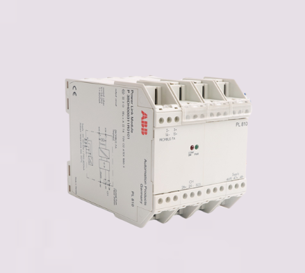
ABB PL810 3BDH000311R0101
I. Overview
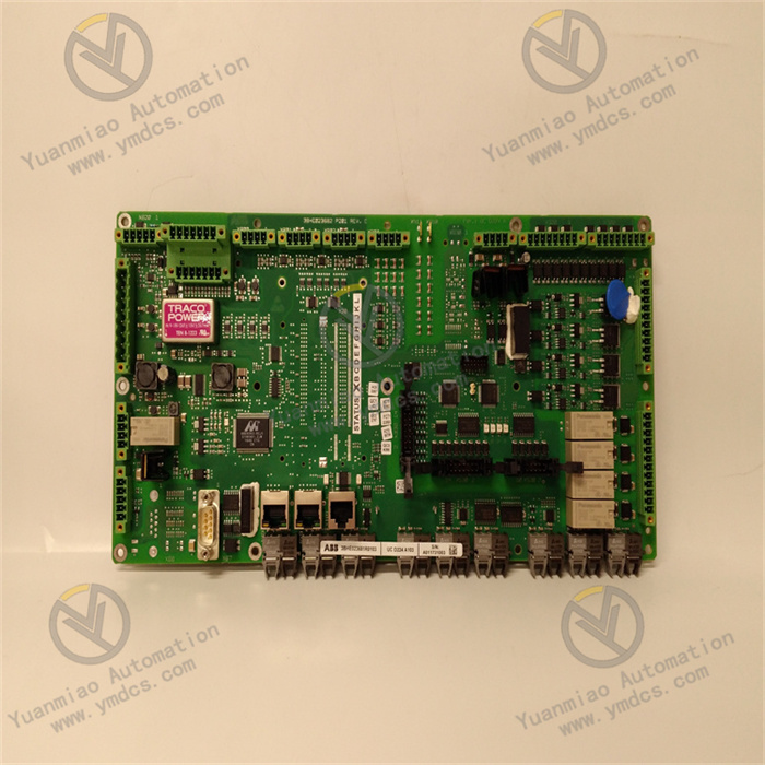
ABB PL810 3BDH000311R0101 is a high-performance digital input module designed for industrial automation control systems. As a core peripheral component of PLC systems, it is responsible for the collection, isolation and transmission of field digital signals (such as switch status, limit signals, etc.). Adopting ABB's industrial-grade standardized design, this product features excellent signal isolation performance and anti-interference capability, and can be seamlessly integrated into ABB AC800M and other series of PLC systems. It serves as a core supporting component to ensure that the control system accurately acquires the status information of field devices.
II. Product Features
High-precision Digital Signal Acquisition: Adopting advanced optoelectronic isolation and signal shaping circuit design, it can accurately collect multi-channel field digital signals, effectively suppress signal jitter and electromagnetic interference, and has fast signal acquisition response speed. It ensures that the PLC system can obtain the real status of field devices in real time and guarantees the accurate execution of control logic.
High-reliability Industrial-grade Architecture: Complying with ABB's core design standards for industrial automation components, it selects high-quality industrial-grade components and undergoes strict environmental stress screening (high and low temperature cycle, vibration and shock tests) and reliability verification. It has excellent anti-electromagnetic interference capability and operational stability, greatly reducing the failure probability in complex industrial environments.
Comprehensive Signal Isolation and Protection Mechanism: Built-in optoelectronic isolation circuits between channels (isolation voltage ≥ 2500V AC) effectively avoid signal interference between channels. It is equipped with signal overvoltage protection and short-circuit protection functions, which can monitor the status of input signals in real time. When abnormal voltage or short circuit is detected, it will automatically isolate the faulty channel to prevent the expansion of faults from damaging the module itself and the PLC master control unit.
Good System Compatibility: Adopting standardized interface and rack mounting size design, it can be seamlessly adapted to ABB AC800M and other series of PLC systems, supports fast networking with PLC master control units, has flexible system integration capability, and simplifies the process of accessory replacement and system expansion.
- Convenient Operation, Maintenance and Installation: Adopting modular plug-and-play design, the installation steps are simple and it can be put into use quickly without complex debugging. The interface marking is clear and it is equipped with intuitive channel status indicator lights, which facilitate operation and maintenance personnel to monitor the signal acquisition status of each channel in real time, quickly locate faulty channels and effectively shorten maintenance downtime.
III. Technical Parameters
1. Core Basic Parameters
- Product Model: PL810 3BDH000311R0101
- Product Series: ABB AC800M PLC Supporting I/O Module Series
- Product Type: Industrial-grade Digital Input Module
- Manufacturer: ABB (ASEA Brown Boveri)
- Place of Origin: Switzerland
- Mounting Method: Standard Rack Mounting (compatible with ABB AC800M system standard racks)
- Core Functions: Digital Signal Acquisition, Signal Isolation, Fault Alarm, Status Feedback
- Application Scenarios: Industrial automation production lines, power and metallurgical equipment control, chemical process management, water treatment systems, large-scale mechanical equipment control, etc.
2. Electrical Performance Parameters
- Working Power Supply: 24V DC (wide voltage input, compatible with 20-28V DC, suitable for industrial standard power supply environment)
- Number of Input Channels: 16-channel digital input (independent channel design, supporting simultaneous acquisition)
- Input Signal Type: Universal for dry contacts/wet contacts (supporting PNP/NPN two-polarity input)
- Input Voltage Range: 18-30V DC (for wet contact input); dry contact input resistance ≤ 100Ω
- Signal Response Time: ≤ 1ms (standard response mode), configurable high-speed response mode (≤ 0.1ms)
- Isolation Method: Optoelectronic isolation between channels, isolation voltage ≥ 2500V AC (for 1 minute continuously)
- Insulation Resistance: ≥ 100MΩ (at 500V DC)
- Power Consumption: Typical value ≤ 5W (no-load state), maximum value ≤ 8W (full-channel working state)
3. Environmental and Physical Parameters
- Operating Temperature: -25℃ to +70℃ (wide-temperature design, suitable for extreme industrial environments)
- Storage Temperature: -40℃ to +85℃
- Relative Humidity: 5% to 95% (no condensation, suitable for high-humidity industrial scenarios)
- Protection Class: IP20 (module body, suitable for installation in control cabinets, dust-proof and foreign object intrusion prevention)
- Electromagnetic Compatibility: Compliant with EN 55022/EN 55024 industrial electromagnetic compatibility standards, with strong anti-electromagnetic interference capability
- Module Dimensions: Standard rack mounting dimensions (44mm width × 100mm height × 180mm depth, subject to the actual product)
- Weight: Approximately 0.5-0.8kg (subject to the actual product)
IV. Working Principle
Stage 1: Power Input and Protection Stage
External industrial power supply (mainly 24V DC, compatible with 20-28V DC wide voltage) is connected to the module through a standardized interface. The built-in power protection circuit of the module provides overvoltage, overcurrent and reverse connection protection for the input power supply, filters out clutter and interference signals in the power supply, avoids damage to subsequent signal processing circuits caused by abnormal power supply, and ensures the stability and safety of the module's power supply.Stage 2: Field Signal Acquisition Stage
The module collects field digital signals in real time through 16 independent input channels, including dry contact signals (such as mechanical switch and limit switch status) and wet contact signals (such as high and low level signals actively output by sensors). The input circuit performs preliminary filtering on the collected signals to remove high-frequency noise in the signals and provide a clean signal source for subsequent processing.Stage 3: Isolation, Conditioning and Logic Conversion Stage
The collected signals enter the optoelectronic isolation unit, which realizes electrical isolation between the input signals and the module's internal circuits through optocouplers, effectively avoiding the impact of strong field electromagnetic interference and ground potential difference on the module and the PLC master control unit. The isolated signals are processed by the shaping and conditioning circuit and converted into standard digital logic signals (0/1) to ensure the stability and consistency of the signals.Stage 4: Data Buffering and Communication Transmission Stage
The converted standard logic signals are temporarily stored in the module's internal data buffer area. Through the dedicated communication bus between the module and the PLC master control unit (compatible with ABB AC800M system bus protocol), the signal status data of 16 channels are uploaded to the PLC master control unit in batches. At the same time, it receives configuration commands issued by the master control unit (such as response time adjustment, fault diagnosis commands, etc.) to complete module parameter configuration.Stage 5: Status Monitoring and Feedback Stage
The module has a built-in status monitoring circuit that collects key parameters such as the signal status of each channel, module working voltage and module temperature in real time. It intuitively feeds back the signal acquisition status (normal acquisition/no signal/fault) through the channel status indicator lights (each channel corresponds to an independent indicator light). At the same time, it supports uploading module fault information (such as power supply abnormality, channel short circuit, etc.) to the PLC master control unit and operation and maintenance terminal through the communication bus, facilitating operation and maintenance personnel to detect and handle faults in a timely manner and ensuring the safety of signal acquisition.V. Common Fault Troubleshooting
1. No Signal Acquisition by Channel/Status Indicator Light Not On
- Disconnect the power supply, check the wiring between the corresponding channels and field devices, correct wrong wiring, re-plug and fasten the connectors to ensure reliable connection.
- Test the performance of field sensors/switches separately, connect a standard signal source (24V DC power supply) to the channels to verify whether the channels can collect signals normally; if the sensors are faulty, replace them with the same type of sensors.
- Use a multimeter to measure the working power supply voltage of the module to ensure stable output within the range of 20-28V DC, and fix the voltage fluctuation problem.
- Disconnect the power supply, check the input fuses of the corresponding channels; if the fuses are blown, replace them with fuses of the same specification and test again.
- If the above measures are ineffective, the built-in optoelectronic isolation circuit of the module may be faulty, and it is necessary to contact professional maintenance personnel or suppliers for inspection and repair.
2. Abnormal Signal Acquisition/Mis-triggering by Channel
- Replace the signal lines with shielded cables, with the shielded layer grounded at one end (grounding resistance ≤ 4Ω), separate wiring from power cables (spacing at least 30cm), and keep away from strong electromagnetic interference sources such as frequency converters and high-power relays.
- Check the wiring of the corresponding channels, re-fasten the connectors, replace aging or damaged lines to ensure no virtual connection in the wiring.
- Check the grounding condition of the module to ensure that the module's grounding terminal is reliably grounded and improve the system grounding loop.
- Adjust the module channel response time through PLC configuration software, switch from high-speed response mode to standard response mode to avoid mis-acquisition of interference signals.
- Check the voltage of the field signal source to ensure stable output within the range of 18-30V DC, and install a filter device if necessary.
- If the problem persists, the built-in signal conditioning circuit of the module may be faulty, and it is necessary to contact professional personnel for inspection, repair or module replacement.
3. Module Fails to Communicate with PLC Master Control Unit
- Disconnect the power supply, check the wiring of the communication bus between the module and the PLC master control unit, correct wrong wiring, fasten loose connectors and replace damaged lines.
- Verify the module address setting to ensure it is consistent with the address configuration in the PLC configuration software to avoid address conflicts.
- Confirm that the communication bus terminal resistance is configured correctly (120Ω terminal resistance should be configured at both ends of the bus) and check whether the resistance is intact.
- Use a multimeter to measure the working power supply voltage of the module to ensure stable output within the range of 20-28V DC, and fix the voltage fluctuation problem.
- Replace the communication bus lines with shielded cables, strengthen the grounding of the shielded layer and keep away from strong electromagnetic interference sources.
- If the above measures are ineffective, the built-in communication chip of the module may be faulty, and it is necessary to contact professional maintenance personnel for inspection and repair.
4. Module Overheating/Simultaneous Failure of Multiple Channels
- Disconnect the power supply immediately, check the field ambient temperature; if it exceeds 70℃, install a cooling fan or improve ventilation conditions, and keep the module at a safe distance (at least 30cm recommended) from high-power heat-generating equipment.
- Clean dust and debris on and around the module to ensure unobstructed heat dissipation channels and avoid blocking the heat dissipation parts of the module.
- Measure the input power supply voltage to ensure stable output within the range of 20-28V DC, and fix the problem of excessively high voltage.
- Check the wiring of all channels, find and repair short-circuited faulty channels, and replace faulty field equipment.
- If the module still gives overheating alarms frequently, the built-in heat dissipation components or power supply circuits may be faulty, and it is necessary to stop using the module and contact professional maintenance personnel for treatment.
VI. Notes
Before installing, wiring, operating or maintaining the module, all input power supplies and signal lines must be disconnected, and the module must be allowed to cool down completely (at least 5 minutes) to avoid the risk of high-voltage electric shock or signal short circuit; it is strictly prohibited to plug/unplug the module or adjust the wiring when it is powered on to prevent damage to the module's internal circuits or the PLC master control unit.
During installation, ensure that the module is completely fixed to the rack and all mounting screws are tightened; sufficient heat dissipation space must be reserved around the module (it is recommended to reserve at least 10cm on both sides and 15cm on the top), and avoid installing it close to high-power heat-generating equipment to prevent overheating from affecting operational stability; in scenarios with large vibrations, anti-vibration fixing devices should be installed to reduce the impact of vibration on the module.
During wiring, strictly distinguish between power interfaces, signal input interfaces and communication interfaces, and wire according to the module interface marking specifications; shielded cables should be preferred for signal lines, with the shielded layer grounded at one end to ensure reliable grounding; power lines, signal lines and communication lines should be wired separately and kept away from strong electromagnetic interference sources to reduce mutual interference.
During the operation of the module, it is necessary to regularly monitor key parameters such as the module's working voltage, channel signal status and module temperature to ensure that all parameters are within the normal range; conduct a comprehensive inspection of the module interfaces and lines every 3-6 months, clean dust, fasten loose connectors and replace aging lines in a timely manner; regularly verify the module parameters through PLC configuration software to ensure consistent configuration.
When replacing the module, ABB genuine PL810 3BDH000311R0101 modules must be used, and it is strictly prohibited to use alternative products with inconsistent models or poor quality; after replacement, re-verify the wiring and communication parameter settings, test the signal acquisition accuracy of each channel, and confirm that the module is working normally before putting it into formal operation.
- When the module is idle for a long time, it should be stored in an environment with a temperature of -40℃ to +85℃, dry and ventilated, and free of corrosive gases to avoid performance degradation of the module caused by moisture, high temperature, collision or chemical corrosion; before storage, all wiring should be removed and interface protection should be done well to prevent dust from entering the module interior.