Description
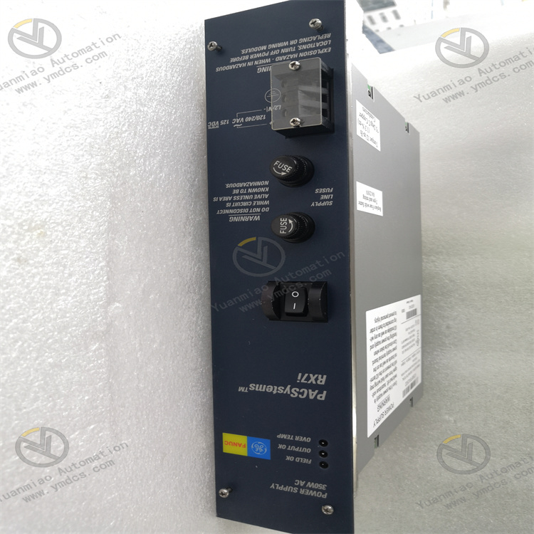
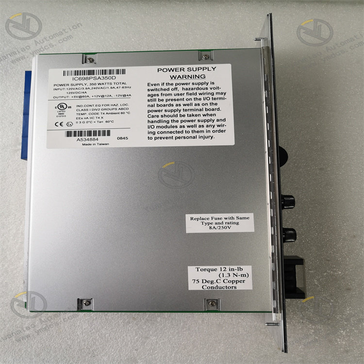
GE IC698PSA350
I. Product Overview
II. Functional Features
Wide Voltage Input and High-Power Output
Adopting advanced LLC resonant topology and synchronous rectification technology, it achieves a power conversion efficiency of up to 92%, with an output ripple voltage ≤30mVp-p and a voltage regulation rate ≤±0.5%. It can effectively suppress grid fluctuations, harmonic interference and load mutations, providing pure and stable power supply for precision control modules and ensuring the accuracy of complex control logic and large-data-volume processing.
Redundant Power Supply and Intelligent Current Sharing
It supports hot-swappable function. The module can be inserted and removed for replacement without shutting down the system and cutting off the main power supply, which greatly shortens maintenance time and improves system operation and maintenance efficiency and availability.
Industrial-Grade Reliability and Anti-Interference Design
Using industrial-grade high-temperature resistant components and sealed protection design (IP20), it has an operating temperature range of -40℃~+70℃, a storage temperature range of -55℃~+100℃ and a humidity tolerance of 5%-95% (non-condensing). With a Mean Time Between Failures (MTBF) of ≥300,000 hours, it can operate stably for a long time in harsh environments such as high temperature, high humidity and heavy dust.
Multiple Protection and Fault Early Warning
It supports digital feedback of fault information. Through the RX7i backplane bus, fault types (overvoltage/overcurrent/overtemperature, etc.) and working status (output voltage/current/temperature) are uploaded to the CPU module and upper-level system, facilitating remote real-time monitoring and precise fault location by operation and maintenance personnel.
High Efficiency, Energy Saving and Convenient Operation & Maintenance
III. Technical Parameters
| Category | Specific Parameters |
|---|---|
| Product Type | RX7i Series High-Power Industrial Redundant Power Supply Module |
| Core Functions | High-power supply, redundant backup, intelligent current sharing, multiple protection, hot-swappable support |
| Input Parameters | AC input: 85~264VAC (50/60Hz); DC input: 120~370VDC; Input current: ≤12A (230VAC) |
| Output Parameters | Output voltage: 24VDC±5%; Continuous output current: 20A; Peak output current: 25A (sustained for 5s); Output ripple: ≤30mVp-p; Voltage regulation rate: ≤±0.5% |
| Conversion Efficiency | ≥92% (full load); ≥88% (50% load) |
| Redundancy Function | Supports N+1 redundancy (up to 4 modules in parallel); Current-sharing error ≤±3%; Switching time ≤5ms |
| Protection Functions | Overvoltage Protection (OVP), Overcurrent Protection (OCP), Short-circuit Protection (SCP), Overtemperature Protection (OTP), reverse connection protection, overtemperature early warning |
| Hot Swap | Supports hot swapping with power on |
| Environmental Adaptability | Operating temperature: -40℃~+70℃; Storage temperature: -55℃~+100℃; Humidity: 5%-95% (non-condensing); Vibration: 10g (10-2000Hz); Shock: 25g (11ms) |
| Installation Method | RX7i series standard backplane installation (dual-slot design) |
| Dimensions | 260mm (L) × 140mm (W) × 80mm (H) (excluding connectors) |
| Weight | Approximately 2.8kg |
| Status Indicators | PWR (Power Normal, Green), FAULT (Fault Alarm, Red), RED (Redundancy Status, Yellow), SHARE (Current-sharing Normal, Green) |
| Power Consumption Characteristics | Full-load power consumption: ≤600W; No-load power consumption: ≤8W |
IV. Working Principle
Wide-Voltage Rectification: External AC (or DC) input power is connected through the module terminals. The AC voltage is converted into stable DC bus voltage by the full-bridge rectifier circuit, and the electromagnetic interference on the input side is filtered out by the EMI filter circuit to ensure pure input power.
- Power Conversion: The DC bus voltage is converted into high-frequency AC signal by the LLC resonant converter, and voltage isolation and step-down are realized by the high-frequency transformer. Then the high-frequency AC signal is converted into DC voltage by the synchronous rectifier circuit, achieving efficient power conversion and voltage level adjustment.
Filtering and Voltage Stabilization: The converted DC voltage is filtered to remove ripples and noise by the LC low-pass filter circuit. Meanwhile, the high-precision feedback control circuit monitors the output voltage in real time and dynamically adjusts the operating frequency of the LLC resonant converter to ensure that the output voltage is stabilized within the range of 24VDC±5%, without being affected by input voltage fluctuations and load changes.
Intelligent Current Sharing and Load Power Supply: In redundant configuration, multiple modules realize real-time monitoring and dynamic adjustment of output current through the current-sharing bus to ensure uniform distribution of load current among all modules. The stable 24VDC output supplies power to load components such as CPU modules and I/O modules through the RX7i backplane bus, meeting the high-power supply requirements of each module.
- Fault Protection and Early Warning: The built-in multi-channel monitoring circuit of the module monitors parameters such as input voltage, output current and module temperature in real time. When an abnormality is detected, the corresponding protection mechanism (output cutoff, current limiting or early warning) is triggered immediately, and the fault information is uploaded to the system at the same time. In redundant configuration, the remaining modules automatically take over the load to ensure power supply continuity.
V. Operation Guide
1. Installation Steps
Mechanical Installation:
- Confirm that the main power supply of the control cabinet is cut off. Insert the module into the designated power slot of the RX7i backplane (dual-slot design), ensure that the module is fully attached to the backplane contacts, lock it with the fixing screws on both sides, and install it firmly without loosening. For redundant configuration, insert multiple modules into adjacent power slots to ensure normal connection of the current-sharing bus between modules.
- Before hot-swappable operation, confirm that the system has enabled redundancy mode to avoid power supply interruption caused by plugging and unplugging when the module is running alone.
Wiring Specifications:
- Input Wiring: For AC input, connect the L and N phase lines to the "AC IN" terminals of the module, and connect the PE ground wire to the ground terminal. For DC input, connect the positive and negative poles to the "DC IN" terminals (note polarity matching; the reverse connection protection function can prevent damage caused by wrong connection). Use 4mm² copper core cables for input wiring, with the shield layer grounded at one end (grounding resistance ≤4Ω).
- Output Wiring: The module automatically supplies power to the load through the RX7i backplane without additional output wiring. Before installation, check whether the backplane power supply bus is intact without short circuit, oxidation or loosening.
- Grounding Treatment: Reliably connect the module's grounding terminal to the protective ground and system signal ground of the control cabinet to form a single-point grounding system with a grounding resistance ≤4Ω, enhancing anti-interference capability and equipment safety.
2. Configuration and Debugging
- Single-Module Configuration: Insert directly into the power slot, confirm that the input voltage matches the module input range (85~264VAC or 120~370VDC), no additional hardware configuration is required. Before first use, check the module firmware version to ensure compatibility with the system.
- Redundant Configuration: Insert 2~4 IC698PSA350 modules of the same model and firmware version into adjacent power slots. The modules automatically realize redundancy negotiation through the backplane current-sharing bus without additional synchronization cables. Confirm that the backplane supports redundant power supply function, and the total load current does not exceed the sum of the rated output currents of all modules.
Power-On Debugging:
- Before the first power-on, check the input voltage polarity and wiring to ensure correctness, and inspect whether the module is installed firmly and the heat dissipation channel is unobstructed.
- Turn on the input power and observe whether the PWR light of the module is always on (green), the SHARE light is always on (current-sharing normal), and the RED light is on according to the redundancy configuration status (off in single-module mode, on for standby modules in redundant configuration). If the FAULT light is always on, cut off the power immediately and troubleshoot the wiring or input voltage issues.
Load Test: Connect loads such as CPU modules and I/O modules, measure the voltage of the backplane power supply terminal with a multimeter (which should be within the range of 22.8~25.2VDC), monitor the output current and temperature of the module to ensure no overload or overheating. In redundant configuration, record the current distribution of each module; the current-sharing error should be ≤±3%.
- Redundancy Switching Test: After normal load operation, disconnect the input power of each module in turn, observe whether the remaining modules automatically take over the load, and whether the system works normally without power supply interruption or data loss. After the test, restore the power supply of all modules and confirm that the current-sharing function is restored normally.
- Hot-Swappable Test: In redundant configuration, plug and unplug one of the modules when the system is running, observe whether the system is stable during the plugging and unplugging process without fault alarm or load power failure, and whether the module can automatically join the redundant system and realize current sharing after plugging.
3. Operation and Maintenance
- Normal Status: PWR light is always on (green), SHARE light is always on (green), RED light is on according to redundancy configuration (standby module), FAULT light is off, module temperature ≤65℃, output voltage is stable within 24VDC±5%.
- Fault Status: FAULT light is always on (red). Locate the fault cause by combining the fault prompts from the upper-level system (such as overvoltage/overcurrent/overtemperature). When overtemperature early warning is triggered, the module temperature indicator light flashes, and the heat dissipation environment needs to be checked in a timely manner.
Regular Maintenance:
- Monthly: Clean dust on the module surface and connector contacts with dry compressed air, check whether the module is installed firmly, and whether the input terminals are loose or oxidized. View the module working parameters (output voltage/current/temperature) through the upper-level system to ensure they meet the requirements.
- Every 6 Months: Check whether the insulation layer of the input cable is damaged or aging, and whether the grounding is reliable. Test the reliability of the redundancy switching function and hot-swappable function. Check whether the cooling system of the control cabinet is running normally without jamming or noise.
- Annually: Fully test the module's performance parameters such as output ripple, conversion efficiency and current-sharing error. Check whether the internal capacitors, heat sinks and fans (if any) of the module are aging, replace the module if necessary. Update the module firmware to the latest version to optimize performance and compatibility.
Notes:
- Hot-swappable operation of the module is prohibited in non-redundant configuration to avoid system power supply interruption. When performing hot-swappable operation in redundant configuration, wear an anti-static wristband to avoid module damage caused by static electricity.
- It is forbidden to use the module beyond the input voltage range and output current limit to avoid triggering the protection mechanism or damaging the module. The total load current shall not exceed the sum of the rated output currents of all redundant modules.
- For modules idle for a long time (more than 6 months), conduct insulation test, withstand voltage test and function verification before commissioning to ensure no abnormalities before connecting to the system.
4. Common Fault Troubleshooting
| Fault Phenomenon | Possible Causes | Troubleshooting Methods |
|---|---|---|
| PWR light off (no output) | Abnormal input voltage, wiring error, module fault, poor backplane contact | Check whether the input voltage is within the range of 85~264VAC/120~370VDC; verify the wiring polarity and terminals; reinsert the module to ensure good contact; test with a spare module |
| FAULT light always on (fault alarm) | Output short circuit, overload, module overtemperature, input overvoltage, current-sharing fault | Troubleshoot whether the load module is short-circuited; reduce the load (total current ≤ sum of the rated output currents of the modules); improve the heat dissipation environment; detect the input voltage; in redundant configuration, check whether the firmware versions of each module are consistent |
| Unstable output voltage | Excessive input voltage fluctuation, aging filter capacitor, load mutation, current-sharing abnormality | Check the grid voltage stability; replace the internal filter capacitor of the module; optimize the load configuration to avoid instantaneous large current impact; recalibrate the current-sharing function in redundant configuration |
| Redundancy switching failure | Inconsistent module model/firmware, backplane does not support redundancy, current-sharing bus fault | Ensure all modules have the same model and firmware version; confirm that the backplane supports redundant power supply; check the connection of the current-sharing bus between modules; reinsert the modules for testing |
| Abnormal module heating | Poor heat dissipation, overload operation, internal fault, fan damage (if any) | Clean the heat dissipation channel and enhance the ventilation of the control cabinet; reduce the load; check whether the internal fan of the module is running normally; detect the internal circuit of the module and replace the module if necessary |
| Hot-swappable failure | Non-redundant configuration, module not locked in place, static interference | Confirm that the system is in redundancy mode; ensure the module is fully inserted into the slot and locked; wear an anti-static wristband during operation to avoid static damage |