Description
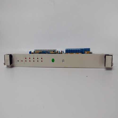
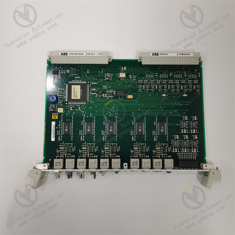
ABB DO820 3BSE008514R1
I. Overview
The ABB DO820 3BSE008514R1 is a digital output module, with its core positioning as a dedicated digital signal output unit for Distributed Control Systems (DCS). Designed specifically for industrial automation scenarios, this module enables precise linkage between controller commands and on-site actuators. It drives executive components such as relays, contactors, and solenoid valves by outputting switching signals to complete control actions including equipment start-stop, valve opening/closing, and alarm triggering.
With its highly reliable industrial-grade design, flexible configuration, and excellent anti-interference capability, it is widely used in core industrial fields such as power generation, chemical engineering, metallurgy, water treatment, papermaking, and rail transit. It seamlessly integrates with the ABB AC 800M control system, providing key signal transmission support for the stable operation of automated production lines, and serves as an important basic component in the industrial distributed control system.
II. Product Features
High-density Multi-channel Design: The single module integrates 16 independent digital output channels with a grouped layout. Each channel can be independently controlled and diagnosed, greatly improving space utilization and adapting to complex control scenarios with multi-actuator linkage. The channels support two output modes: Normally Open (NO) and Normally Closed (NC), which can be flexibly configured through configuration software to meet the control requirements of different actuators.
High Reliability and Redundant Protection: It adopts industrial-grade high-stability components and supports redundant power supply design, effectively avoiding module outage caused by single power supply failure and ensuring the continuity of the control link. Each channel has built-in overcurrent protection and short-circuit protection functions, which can automatically resist abnormal working conditions such as load overload and line short-circuit, prevent module damage and fault spread, and extend the service life of the equipment.
Flexible Configuration and Rapid Integration: It seamlessly integrates with the ABB AC 800M controller, supporting channel parameter configuration, fault threshold setting, and linkage logic programming through the Control Builder configuration software with an intuitive and easy-to-operate interface. The module adopts a standardized bus interface, which can be quickly connected to the distributed control system and supports hot-swapping function. Module replacement and maintenance can be completed without shutdown, minimizing production interruption.
Strong Anti-interference and Environmental Adaptability: It has excellent Electromagnetic Compatibility (EMC), passing rigorous electromagnetic interference tests. Adopting shielded design and signal isolation technology, it can effectively resist strong electromagnetic radiation, voltage fluctuations and other interferences in industrial sites, ensuring signal transmission stability. With an IP20 protection rating, it adapts to industrial environments with dust, humidity, and alternating high and low temperatures. The operating temperature range covers -25℃ ~ +60℃, meeting the requirements of various harsh working conditions.
Comprehensive Fault Diagnosis and Status Feedback: It has a built-in complete self-diagnosis function, which can real-time monitor the working status of each channel (normal, short-circuit, overload, open-circuit). Upon detecting a fault, it immediately generates a fault code and feeds it back to the upper controller, and intuitively indicates the fault location through the module indicator light. It supports real-time channel status readback, facilitating remote monitoring and rapid fault troubleshooting by operators and improving operation and maintenance efficiency.
- High Standardization and Versatility: It complies with the IEC 61131-2 industrial standard, being compatible with the installation guide rails and communication protocols of ABB S800 I/O series modules. It can be flexibly combined with input modules and analog modules of the same series to adapt to the expansion needs of different automation control scenarios. The output signal conforms to industrial general standards, being compatible with mainstream brand actuators on the market and having strong versatility.

III. Technical Parameters
1. Core Basic Parameters
- Product Model: ABB DO820 3BSE008514R1
- Product Type: Industrial-grade Digital Output Module (DO Module)
- Brand Series: S800 I/O Series Supporting ABB AC 800M Controller
- Core Functions: 16-channel digital signal output, independent channel control, fault self-diagnosis, overcurrent/short-circuit protection, hot-swapping
- Compatible System: ABB AC 800M Distributed Control System
- Compatible Actuators: Relays, contactors, solenoid valves, indicator lights, small motors, etc.
- Application Fields: Power generation, petrochemical industry, metallurgical smelting, water treatment, papermaking and printing, rail transit, intelligent manufacturing, etc.
2. Electrical Performance Parameters
- Supply Voltage: 24 VDC (allowable fluctuation range: 19.2V DC ~ 28.8V DC), supporting redundant power supply
- Number of Output Channels: 16 independent digital output channels, divided into 2 groups (8 channels per group)
- Output Type: Transistor Output (MOSFET)
- Output Mode: Normally Open (NO)/Normally Closed (NC) configurable switching
- Maximum Output Current per Channel: 0.5A (continuous), 2A (peak value, duration ≤ 100ms)
- Output Voltage Range: 24 VDC (compatible with rated load voltage)
- Response Time: ≤ 1ms (turn-on time), ≤ 1ms (turn-off time)
- Communication Interface: Communicates with AC 800M controller via S800 I/O bus
- Isolation Method: Electrical isolation between channels, photoelectric isolation between module and bus (isolation voltage ≥ 2500V AC)
- Protection Functions: Overcurrent protection, short-circuit protection, and reverse connection protection for each channel
3. Environmental and Physical Parameters
- Operating Temperature: -25℃ ~ +60℃
- Storage Temperature: -40℃ ~ +85℃
- Relative Humidity: 5% ~ 95% RH (non-condensing)
- Protection Rating: IP20 (panel-mounted, compliant with IEC 60529 standard)
- Dimensions: 100mm (length) × 160mm (width) × 80mm (height) (compatible with S800 I/O standard guide rails)
- Weight: Approximately 0.35 kg
- Mounting Method: 35mm DIN rail mounting (compliant with EN 60715 standard), supporting hot-swapping
- Vibration Resistance: Frequency 10-500Hz, acceleration 2g (sine wave), compliant with IEC 60068-2-6 standard
- Shock Resistance: Acceleration 15g, duration 11ms, compliant with IEC 60068-2-27 standard
IV. Working Principle
The core working principle of the ABB DO820 3BSE008514R1 digital output module is a closed-loop control process of upper-level command receiving - signal conversion and amplification - actuator driving - status feedback and diagnosis. Through the coordinated operation of the bus communication module, channel driving module, protection module and diagnosis module, it realizes precise linkage between the controller and on-site actuators. The specific working process can be divided into four core stages:
Stage 1: Command Receiving StageThe module establishes stable communication with the ABB AC 800M controller via the S800 I/O bus, and real-time receives digital control commands (high-level/low-level signals) issued by the upper controller. The communication module verifies and decodes the received command signals, eliminates interference clutter during bus transmission, ensures the integrity and accuracy of the command signals, and feeds back the module's own working status to the upper controller to achieve two-way data interaction.
Stage 2: Signal Conversion and Amplification StageThe decoded control commands are transmitted to the channel driving module. The MOSFET transistors inside the driving module convert the weak electric command signals into strong electric switching signals that can drive the actuators. According to the configured output mode (NO/NC), the transistors of the corresponding channels are turned on or off to output 24VDC control signals. Meanwhile, the current amplification circuit ensures that the output current meets the rated requirements of the actuators, realizing the conversion from weak electric commands to strong electric driving.
Stage 3: Actuator Driving StageThe amplified digital output signals are transmitted to on-site actuators (relays, solenoid valves, etc.) through the module terminals, driving the actuators to complete preset actions (such as relay pull-in, solenoid valve opening). During the driving process, the module real-time monitors the output current and voltage status of each channel. If abnormal working conditions such as overload or short-circuit are detected, the protection mechanism is triggered immediately to cut off the output of the corresponding channel, preventing component damage and fault spread.
V. Common Fault Troubleshooting
1. No Output Signal from the Module and No Action of Actuators
- Detect the module supply voltage to ensure stable 24VDC power supply with a fluctuation range of 19.2V ~ 28.8V. Check the connection of the redundant power supply. If a single power supply fails, switch to the backup power supply and troubleshoot the faulty power supply.
- Check the bus line connection, re-tighten the connectors, and use a multimeter to test the line continuity. Verify the communication protocol configuration between the module and the controller to ensure consistent parameters, and restart the module and controller to restore communication.
- Verify the correctness of the terminal wiring, correct the reverse connection of positive and negative poles, re-plug the terminals to ensure good contact, and repair the open-circuit lines.
- Disconnect the connection between the module and the actuator, test the continuity of the actuator separately, and replace the actuator in a timely manner if it fails.
- Replace the backup module or switch to an idle channel for testing. If the backup channel/module outputs normally, it is determined that the driving transistor of the original channel is damaged. Contact ABB official after-sales service for maintenance or module replacement.
2. The Module Frequently Triggers Overcurrent/Short-circuit Protection
- Verify the rated current of the actuator to ensure it does not exceed the maximum load of the module channel. If the load is too large, install an intermediate relay to drive the actuator through the relay to avoid direct loading of the module.
- Detect the insulation performance and continuity of the actuator. If there is an internal short-circuit in the actuator, replace the actuator immediately.
- Clean the oxide layer of the terminals, re-tighten the wiring to ensure reliable line connection; check whether the line insulation layer is damaged, repair the damaged parts to avoid line short-circuit.
- Improve the module installation environment, reduce environmental humidity, and avoid water vapor intrusion into the module; check the module grounding condition to ensure reliable grounding and reduce leakage risk.
3. Communication Interruption Between the Module and the Controller
- Disconnect the power supply, check the connection of the bus line connectors, re-tighten the connectors, use a multimeter to test the line continuity, and repair the open-circuit parts. Ensure that the bus lines are not routed in parallel with the power lines to avoid strong electric crosstalk.
- Replace the shielded bus cable, reliably ground the shield layer at one end (grounding resistance ≤ 4Ω), keep away from strong electromagnetic interference sources such as high-power equipment in industrial sites, and enhance anti-interference capability.
- Verify the module address through the configuration software, modify the conflicting address to ensure a unique address for each module, and restart the module and controller to take effect.
- Replace the backup module and connect it to the bus. If the backup module can communicate normally, it is determined that the communication interface of the original module is damaged. Contact ABB after-sales service for maintenance.
- If multiple modules cannot communicate, troubleshoot the controller bus interface fault, repair or replace the controller bus module.
4. The Module Fails to Work Normally After Hot-swapping
- Re-plug the module according to the standard process: first cut off the module power supply, then pull out the module, check whether the module pins and guide rail contacts are oxidized or damaged, clean the oxide layer and reinsert it to ensure reliable contact, and then restore the power supply.
- Check the bus connector, re-tighten the loose connector during plugging and unplugging, and repair the damaged connector.
- Refresh the controller module configuration information through the configuration software, restart the controller and the module to ensure the controller recognizes the module and loads the configuration parameters.