Description
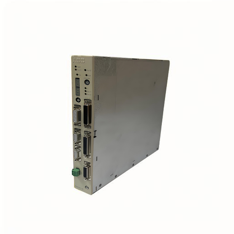
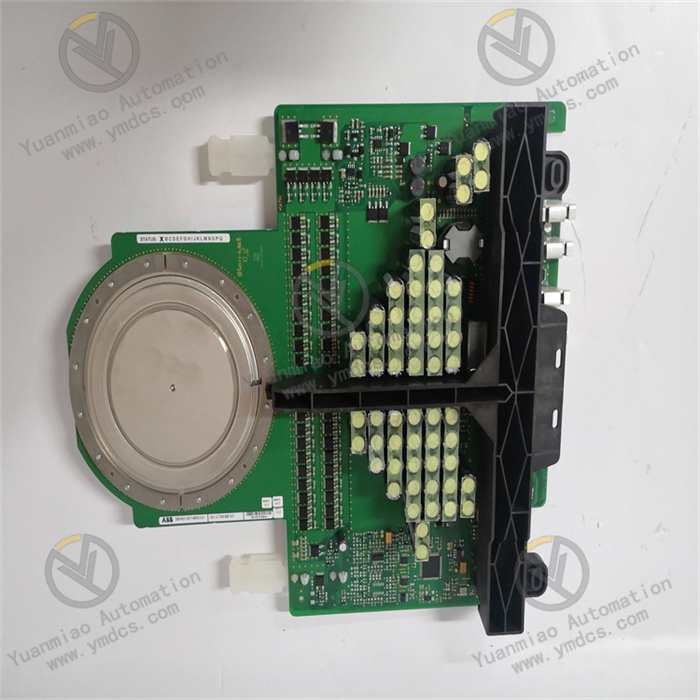
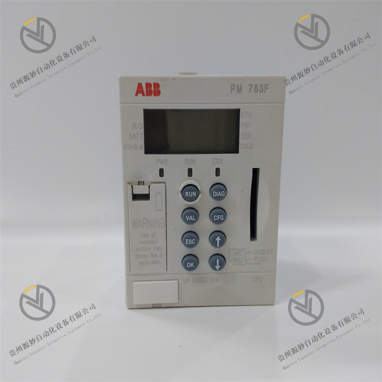
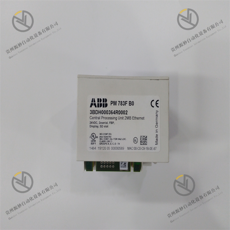
ABB PM783F 3BDH000364R0002
I. Product Overview
II. Functional Features
Multi-core High-performance Computing and Complex Control Capability
- Equipped with a dual-core 64-bit industrial-grade processor with a main frequency of 1.2GHz, 1GB RAM (for program and data storage), and 512MB Flash storage, it supports the simultaneous operation of 4,000 function blocks and 320 control loops. It can parallel process complex tasks such as logic control, PID regulation, cascade control, batch control, and sequence control, meeting the multi-parameter and high-concurrency control requirements of large-scale industrial systems.
- The control cycle can be precisely configured (minimum 0.5ms), the logic operation response time is ≤0.05ms per 1,000 steps, and the process regulation accuracy reaches ±0.01%, making it suitable for fast-response control scenarios (such as thermal power boiler combustion control and chemical reactor temperature regulation).
- It is compatible with IEC 61131-3 standard programming methods (LD, FBD, ST, IL, SFC) and ABB Control Builder Plus graphical programming software, supporting the rapid development, simulation, and debugging of complex control algorithms, as well as program migration from Symphony legacy systems.
Dual Redundancy and Ultra-high Reliability Design
- Supports 1:1 dual redundant configuration (with built-in redundant synchronization interface). The active and standby controllers synchronize operating data, control logic, and status information in real time through a high-speed optical fiber synchronization bus, with a fault switching time of ≤3ms, ensuring zero interruption of critical industrial processes. The Mean Time Between Failures (MTBF) is ≥800,000 hours.
- Adopts industrial-grade high-stability components and enhanced sealed protection design (IP20), with an operating temperature range of -25℃~+65℃ and a humidity range of 5%-95% (non-condensing). Its vibration and shock resistance performance complies with IEC 60068-2 standards, enabling long-term stable operation in harsh industrial environments with high temperature, high humidity, heavy dust, and strong electromagnetic interference.
- Built-in hardware watchdog, software fault-tolerant mechanism, and comprehensive fault self-diagnosis function, it can real-time monitor the status of key components such as the processor, storage, power supply, communication interface, and I/O channels, provide early warning of potential faults, and support module-level fault location to reduce troubleshooting difficulty.
Full Protocol Support and Cross-system Seamless Integration
- Natively supports a variety of industrial communication protocols: Profinet IO (IRT), Modbus TCP, EtherNet/IP, OPC UA, DNP3.0, IEC 61850, etc. It can be directly integrated with ABB Symphony Plus I/O modules, intelligent instruments, third-party PLCs, and Safety Instrumented Systems (SIS) without additional protocol gateways.
- Supports industrial Ethernet redundancy (MRP/MSTP) and optical fiber redundancy, with a communication rate of 1Gbps, ensuring real-time performance and anti-interference of data transmission. Equipped with 4 independent Ethernet ports (2 for control network, 2 for information network), it achieves physical isolation of control network, information network, and safety network, improving system security and reliability.
- Backward compatible with ABB Symphony Harmony legacy systems, and seamlessly connected to upper-level Symphony Plus operator stations and MES/ERP systems, supporting production data upload, remote monitoring, and scheduling, facilitating industrial digital and intelligent transformation.
Flexible Expansion and Easy Maintenance
- Supports up to 16 local I/O bus interfaces, which can be expanded to connect the full range of Symphony Plus analog, digital, and special function modules (such as AI830A, AO820, DI810, PI830), with a maximum expandable capacity of 1,024 I/O channels, adapting to the control requirements of large-scale industrial installations of different sizes.
- Adopts a modular design and 19-inch 4U standard rack mounting, supporting hot-swapping of the controller, power module, and communication module. Maintenance can be performed without stopping the system, reducing production downtime. The front panel is equipped with color status indicators, an LCD display, and a USB debugging interface, which can real-time display operating status and fault codes, facilitating rapid on-site troubleshooting and program downloading.
- Supports remote maintenance and intelligent diagnosis: realizes remote programming, parameter modification, fault diagnosis, and program backup/restore through Control Builder Plus software, and supports online firmware upgrade of the controller, reducing on-site maintenance costs and workload.
High-precision Process Control and Energy Optimization Capability
- Integrates a wealth of advanced control algorithms: PID regulation (with adaptive auto-tuning function), feedforward control, cascade control, ratio control, Smith predictive control, fuzzy control, etc. It can accurately regulate process parameters such as temperature, pressure, flow, liquid level, and composition, ensuring production process stability and product quality consistency.
- Real-time collects equipment operating data and energy consumption parameters (voltage, current, power, energy consumption), supports energy consumption monitoring, trend analysis, and optimization suggestion output, provides data support for energy optimization configuration, energy conservation, and emission reduction, and helps reduce production and operation costs.
III. Technical Parameters
| Category | Specific Parameters |
|---|---|
| Product Type | High-end redundant process controller of the Symphony Plus series |
| Core Functions | Logic control, process regulation, batch control, sequence control, data interaction, fault self-diagnosis, redundant backup |
| Processor and Storage | Dual-core 64-bit industrial-grade processor, 1.2GHz main frequency; 1GB RAM (program + data); 512MB Flash storage |
| Control Performance | Supports up to 4,000 function blocks and 320 control loops; Control cycle: 0.5ms~10s (configurable); Logic operation response time ≤0.05ms per 1,000 steps |
| Programming Methods | IEC 61131-3 (LD/FBD/ST/IL/SFC); Supports ABB Control Builder Plus software; Compatible with legacy program migration |
| Communication Protocols | Profinet IO (IRT), Modbus TCP, EtherNet/IP, OPC UA, DNP3.0, IEC 61850, IEC 60870-5-104 |
| Communication Interfaces | 4×10/100/1000Mbps Ethernet ports (supporting MRP redundancy); 2×redundant synchronous optical fiber interfaces; 1×USB 3.0 debugging interface; 1×RS-232 maintenance interface |
| Redundant Configuration | Supports 1:1 dual redundancy; Synchronization method: high-speed optical fiber synchronization; Switching time ≤3ms |
| Expansion Capability | Up to 16 local I/O bus interfaces; Maximum expandable to 1,024 I/O channels (compatible with the full range of Symphony Plus I/O modules) |
| Power Supply Parameters | Supply voltage: 24V DC (supporting redundant power supply); Power consumption: 25W (typical), 35W (maximum) |
| Physical Parameters | Dimensions: 19-inch 4U rack-mount (483mm×177mm×300mm); Weight: approximately 5.2kg |
| Environmental Adaptability | Operating temperature: -25℃~+65℃; Storage temperature: -40℃~+85℃; Humidity: 5%-95% (non-condensing); Protection class: IP20; Electromagnetic interference resistance complies with IEC 61000-4 |
| Compatible Systems | ABB Symphony Plus control system; Full range of Symphony Plus I/O modules; Third-party Profinet/IEC 61850 devices; Symphony Harmony legacy system |
| Application Scenarios | Large-scale thermal/nuclear power generating units, petrochemical plants, metallurgical blast furnaces, large-scale water treatment plants, pharmaceutical production lines, large-scale intelligent manufacturing bases |
IV. Working Principle
The core working logic of ABB PM783F 3BDH000364R0002 follows the sequence of "multi-source data collection → multi-core parallel computing → precise control output → redundant synchronous backup → cross-system communication interaction → full-dimensional status diagnosis", with the specific process as follows:
- Multi-source Data Collection: It receives on-site sensor signals (analog/digital/pulse) collected by Symphony Plus I/O modules through local I/O bus interfaces, or operating data from intelligent instruments, safety systems, and third-party devices via protocols such as Profinet/IEC 61850, realizing unified access and preprocessing of multi-source heterogeneous data.
Multi-core Parallel Computing: The dual-core processor parallel processes complex tasks such as logic judgment, PID regulation, cascade control, and sequence control according to preset control logic (implemented through IEC 61131-3 programming). For key parameters, advanced control algorithms (such as Smith predictive control) are adopted to compensate for lag, and the computing results are fed back to the output buffer in real time.
- Precise Control Output: The processed control commands are synchronously output to actuators (valves, motors, control valves, etc.) through I/O modules to realize equipment start-stop and precise parameter adjustment. It supports multi-channel millisecond-level synchronous output, meeting the multi-device collaborative control requirements of large-scale installations (such as thermal power boiler feedwater, combustion, and steam temperature collaborative control).
Redundant Synchronous Backup: In dual redundant mode, the active and standby controllers synchronize operating data, control logic, status information, and output commands in real time through a high-speed optical fiber synchronization bus. When the active controller detects a fault (hardware abnormality, communication interruption, power failure), the standby controller seamlessly takes over control within ≤3ms, ensuring zero interruption of the control process.
- Cross-system Communication Interaction: It conducts data interaction with upper-level Symphony Plus operator stations and MES/ERP systems through Ethernet interfaces, uploading production data, equipment status, fault information, and energy consumption data, and receiving remote control commands and parameter configurations. At the same time, it realizes real-time communication with on-site safety systems and intelligent equipment to ensure system collaboration and safety interlocking.
- Full-dimensional Status Diagnosis: The controller real-time monitors its own hardware status (processor, storage, power supply, communication interface), I/O channel signal validity, and redundant synchronous link integrity. When an abnormality is detected, it triggers local LCD fault display, status indicator alarm, and remote operator station prompt, and uploads detailed fault codes and location information to facilitate rapid troubleshooting.

V. Operation Guide
1. Installation Steps
Installation Environment
Mechanical Installation
- Confirm that the main power supply of the control cabinet is cut off. Fix the controller in the 19-inch 4U rack position and lock it with bolts to ensure firm installation without loosening. For redundant configuration, install the active and standby controllers side by side with a spacing of ≥20mm. The optical fiber synchronization cables must be routed separately to avoid crossing with power cables.
- Connect redundant power modules (ABB PS802 redundant power supply is recommended) to ensure independent power supply for the active and standby power sources (from different power cabinets) to improve power supply reliability. During installation, connect in the order of "controller → bus module → I/O module" to ensure normal bus communication.
Wiring Specifications
- Power Wiring: Connect to 24V DC redundant power supply, strictly distinguish between positive and negative polarities, and fasten the wiring terminals. A 5A fuse is connected in series at the power input end. The power cable is 2.5mm² copper core cable with a length not exceeding 10 meters to ensure power supply stability.
- Communication Wiring: The Ethernet interface is connected to the industrial switch through Cat6A shielded network cable, supporting Profinet redundant network configuration. The optical fiber synchronization interface is connected to the active and standby controllers through single-mode optical fiber, with a fiber bending radius ≥30mm. The RS-232 interface is used for local debugging, and the communication parameters must be matched during connection (baud rate 9600bps, data bits 8, no parity bit).
- Notes: Before wiring, confirm that the power supply voltage matches the rated voltage of the controller to avoid reverse polarity connection. Route communication cables separately from power cables (spacing ≥20cm), and ground the shield layer at one end (grounding resistance ≤4Ω). The redundant optical fiber cables must be routed redundantly (different paths) to prevent simultaneous failure.
2. Configuration and Debugging
Parameter Configuration
- Install ABB Control Builder Plus programming software. Establish a connection with the controller via USB or Ethernet interface, create a new project and add the PM783F controller model, and configure basic parameters such as communication protocols (e.g., Profinet IO, IEC 61850), IP address, I/O module mapping relationship, and redundant parameters.
- Programming and Logic Configuration: Write control logic using IEC 61131-3 standard programming methods, define I/O channel addresses, control parameters (PID proportional gain, integral time, derivative time), safety interlocking logic, and fault response strategies, supporting simulation testing and offline debugging of control logic.
- Redundant Configuration: Enable the redundant function in the software, configure the IP addresses of the active and standby controllers, synchronization method (optical fiber synchronization), and switching strategy (automatic switching), activate the redundant synchronization function, and monitor the synchronization status of the active and standby controllers through the software (steady green light of the synchronization status indicator means normal).
Power-on Debugging
- Before the first power-on, verify the correctness of wiring, and the consistency between the controller model and configuration parameters. Use a multimeter to measure the power supply voltage (24V DC±10%) to confirm there are no short circuits or reverse connections.
- After power-on, observe the status of the controller front panel: steady power indicator (PWR), flashing run indicator (RUN), and steady redundant synchronization indicator (SYNC) indicate normal operation. If the fault indicator (FAULT) is steady on or the LCD displays fault codes, troubleshoot the cause through the software.
- Function Testing: Force the output of control commands through the software and observe whether the actuator actions meet expectations. Input standard signals to test PID regulation accuracy and response time, and verify the execution effect of complex control logic (such as cascade control and sequence control). Simulate an active controller fault (disconnect the power supply) to test whether the redundant switching is completed within ≤3ms and whether the control parameters are stable after switching.
- Communication Testing: Verify the communication connections between the controller and Symphony Plus operator stations, I/O modules, and third-party IEC 61850 devices to ensure real-time data transmission without packet loss. Test the functions of remote parameter modification, program downloading, and firmware upgrading to ensure normal remote maintenance.
3. Operation and Maintenance
Status Monitoring
- Normal Status: Stable power supply, flashing run indicator, normal redundant synchronization, stable control parameters, no fault alarms.
- Fault Status: Steady fault indicator, LCD displaying fault codes (such as hardware fault, communication fault, redundant switching fault), and the operator station prompting fault information. Troubleshooting should be conducted by combining fault codes and wiring status.
Regular Maintenance
- Monthly: Clean dust on the controller surface and interfaces with dry compressed air, check the installation firmness and whether the wiring terminals are loose or oxidized. View operation logs and fault records through the software to analyze potential problems. Check the redundant synchronization status and the operating status of power modules.
- Every 6 Months: Conduct a comprehensive inspection of the insulation layer of power cables, communication cables, and optical fiber cables for damage or aging, and check the reliability of shield layer grounding. Back up control programs and configuration parameters and store them in a safe location (offline backup + cloud backup). Test the redundant switching function and fault self-diagnosis capability to ensure system reliability.
- Annually: Inspect the internal components of the controller for signs of aging (such as swollen capacitors and loose interfaces). Upgrade the controller firmware and programming software to the latest stable versions (back up programs before upgrading). Calibrate I/O channels to ensure measurement accuracy. If the controller experiences problems such as operation lag or frequent faults, replace it with original spare parts in a timely manner.
4. Common Fault Troubleshooting
| Fault Phenomenon | Possible Causes | Troubleshooting Methods |
|---|---|---|
| The controller fails to power on (power indicator is off) | No power input, abnormal voltage, burned fuse, incorrect wiring | Check the access status of 24V DC redundant power supply; Measure whether the voltage fluctuates within ±10%; Replace the 5A fuse; Verify the wiring polarity and integrity |
| The controller cannot be recognized by the software | Faulty communication cable, incorrect IP address configuration, software compatibility issues | Replace the Cat6A communication cable; Reconfigure the controller IP address (to be in the same network segment as the software); Upgrade Control Builder Plus to a compatible version |
| Abnormal execution of control logic | Program error, improper parameter configuration, incorrect I/O mapping | Troubleshoot logic loopholes in the control program; Readjust key parameters such as PID parameters and control thresholds; Verify that the I/O channel mapping is consistent with the actual wiring |