Description
ABB DO814 3BUR001455R1
I. Overview
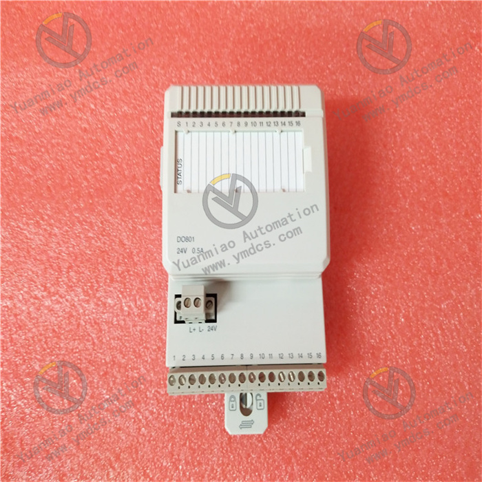
ABB DO814 3BUR001455R1 is a compact 16-channel digital output module specially designed for the S800 I/O system. It is positioned as a precision signal conversion and grouped drive terminal between industrial automation control systems and field execution devices, suitable for decentralized or centralized signal output requirements in small and medium-sized industrial scenarios. This module can stably receive digital control commands issued by ABB control systems such as Freelance and Advant 800xA. Through its internally integrated low-side switch drive circuit and grouped isolation design, it converts the commands into sink current output signals that can directly drive external execution devices, realizing start-stop control and status switching of digital execution devices such as small relays, indicator lights, and micro solenoid valves. It provides stable and reliable signal output support for industrial process automation in industries such as power auxiliary control, light industry manufacturing, and municipal supporting equipment.
II. Product Features
Compact Grouped Channel Design: Adopts a high-density integrated design with 16 channels, which are divided into two groups of independent isolation units (8 channels per group). It realizes drive control of multiple devices in limited installation space, greatly improving cabinet space utilization. The grouped isolation design can effectively avoid signal interference between different channel groups, adapting to scenarios where execution devices of different load types are mixed and connected.
Stable Sink Current Output Performance: The module adopts sink current output mode, with a maximum continuous output current of up to 0.5A per channel and a short-circuit current limit of 2.4A, capable of stably driving small industrial execution devices. Each output channel integrates EMC protection components and inductive load suppression circuits, effectively resisting on-site voltage fluctuations and electromagnetic interference, and ensuring the stability and accuracy of output signals. The channel leakage current is less than 10μA, avoiding false triggering of sensitive execution devices.
Flexible System Adaptability: Tailor-made for the ABB S800 I/O system, it can seamlessly connect with control systems such as Freelance and Advant 800xA. It supports adaptive installation with various terminal units (TU810, TU812, TU814, etc.), meeting the requirements of different wiring and installation scenarios. Data transmission is realized via the module bus with stable communication and low latency. Meanwhile, it supports long-distance field wiring with a maximum cable length of up to 600m, adapting to decentralized installation scenarios.
Comprehensive Grouped Diagnosis and Fault Response: Built-in with grouped voltage monitoring and full-channel fault diagnosis functions, each channel group is equipped with an independent voltage monitoring input, which can real-time monitor the status of on-site process voltage. When voltage is missing, it automatically generates channel error signals and uploads them via the module bus. It has the OSP (Output at Standstill on Power failure) function. When a fault is detected, the output can be set to a preset safe state to avoid device misoperation. It is equipped with status indicator lights such as fault, run, and warning, as well as channel status LEDs, allowing operation and maintenance personnel to intuitively judge the overall status of the module and the working condition of individual channels, and quickly locate fault points.
Reliable Protection and Environmental Adaptability: Each output channel is built-in with short-circuit protection and over-temperature protection circuits. In case of short-circuit or over-temperature faults, it can quickly cut off the output to protect the module and external execution devices from damage. It has passed electromagnetic compatibility certifications such as EN 61000-6-2 and EN 61000-6-4, with strong anti-interference capability. It can operate stably in a working temperature range of 0℃~+55℃ and a humidity environment of 5%~95% RH (no condensation), adapting to most conventional industrial scenarios.
- Convenient Installation and Maintenance Design: Adopts a compact structure design with a weight of only 0.18kg and small dimensions (45×102×119mm), facilitating installation and deployment in limited cabinet space. The standardized module bus interface and terminal unit adaptive design simplify the wiring process. Through intuitive LED indicator lights, it real-time feeds back the module operation status and channel faults. Combined with the controller diagnosis function, it greatly reduces operation and maintenance difficulty and time costs.
III. Technical Parameters
1. Core Basic Parameters
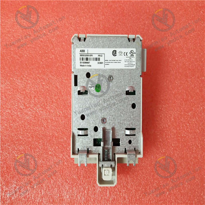
- Product Model: ABB DO814 3BUR001455R1
- Product Type: Compact 16-channel digital output module
- Manufacturer: ABB Group
- Product Series: ABB S800 I/O System Component
- Core Functions: Receive digital commands from controller, sink current signal output, grouped voltage monitoring, short-circuit/over-temperature protection, fault diagnosis and OSP safe state output
- Communication Method: Communicate with controller via module bus, compatible with S800 I/O system bus protocol
- Applicable Systems: ABB Freelance Control System, Advant 800xA Control System
- Compatible Terminal Units: TU810, TU812, TU814, TU830, TU833, TU838
- Application Fields: Power industry (substation auxiliary control equipment), light industry manufacturing (small actuators in production lines), municipal engineering (water supply/sewage treatment auxiliary equipment), building automation (HVAC control components), etc.
2. Electrical Performance Parameters
- Supply Voltage: Module bus powered 5V DC (bus power consumption: 80mA @ +5V)
- Output Type: Digital sink current output, current-limiting type
- Channel Quantity: 16 independent digital output channels, divided into 2 groups (8 channels per group), with electrical isolation between groups
- Output Voltage Range: 12V DC ~ 32V DC (rated output 24V DC)
- Output Current: Maximum continuous output current per channel ≤ 0.5A; short-circuit current limit 2.4A; channel leakage current < 10μA
- Output Impedance: < 0.4Ω
- Output Protection: Short-circuit protection, over-temperature protection, over-voltage protection
- Fault Diagnosis Range: Channel short circuit, over-temperature fault, process voltage loss, module bus communication abnormality
- Special Function: OSP fault preset state output function (output is set to preset safe state in case of fault)
- Maximum Field Cable Length: 600m (compatible with standard industrial cables)
- Insulation Performance: Isolation between groups and ground; rated insulation voltage 50V; dielectric strength 500V AC
- Driven Device Type: Low-load digital execution devices such as small relays, industrial indicator lights, micro solenoid valves, small electromagnetic clutches
3. Environmental and Physical Parameters
- Operating Temperature: 0℃~+55℃
- Storage Temperature: -40℃~+70℃
- Relative Humidity: 5%~95% RH (no condensation)
- Pollution Degree: Degree 2 (compliant with IEC 60664-1 standard)
- Electromagnetic Compatibility: Compliant with EN 61000-6-2 (immunity) and EN 61000-6-4 (emission) standards
- Protection Grade: IP20 (module itself, compliant with IEC 60529 standard)
- Corrosion Resistance: Compliant with ISA-S 71.04 G3 standard
- Safety Certification: Compliant with IEC 61131-2 and UL 508 standards; hazardous area certification: Class I Div 2 (culus), ATEX Zone 2; classification society certification: ABS, BV, DNV-GL, etc.
- Weight: Approximately 0.18kg (module itself); 0.26kg (including basic packaging)
- Installation Method: Rack-mounted installation (compatible with S800 I/O system standard rack)
- Dimensions (Width × Depth × Height): 45mm × 102mm × 119mm (subject to official manual)
- Keying Code: BE
- Power Consumption: Typical value 2.1W
IV. Working Principle
The core working principle of ABB DO814 3BUR001455R1 is a closed-loop workflow of command receiving - signal conversion - grouped drive - status monitoring - fault response. Through the coordinated operation of the communication unit, signal processing unit, grouped output drive unit, and fault diagnosis unit inside the module, it realizes accurate conversion of controller commands and reliable drive of field execution devices. The specific working process can be divided into five core stages:
Stage 1: System Initialization and Parameter Configuration StageAfter the module is installed and connected to the S800 I/O system, it establishes communication connection with the controller via the module bus, automatically completes initialization and startup, performs internal circuit self-test, calibrates 16 output channels one by one, and verifies communication link integrity. Operation and maintenance personnel complete the configuration of basic parameters such as output fault preset state (OSP) and diagnosis threshold through the system configuration software, ensuring the module is precisely adapted to the controller and field execution devices, and meeting the operation requirements of specific control scenarios.
Stage 2: Controller Command Receiving StageBased on the logic operation results of the industrial process, the controller transmits digital control commands (such as device start-stop and status switching commands) to the communication unit of the DO814 module via the module bus. The communication unit parses the command format and verifies validity, filtering invalid commands and interference signals to ensure the accuracy of command transmission.
Stage 3: Signal Conversion and Drive Preparation StageThe verified control commands are transmitted to the signal processing unit inside the module. The processing unit converts the commands into standardized drive signals and triggers the low-side switch circuit of the corresponding channel. Meanwhile, the module real-time monitors the process voltage status of the corresponding channel group, ensuring the supply voltage is within the normal working range, and providing voltage guarantee for subsequent output drive.
Stage 4: Grouped Output Drive and Status Collection StageThe drive signals are transmitted to field execution devices through corresponding output channels, providing working current for the devices by means of sink current output mode, triggering the devices to complete preset actions (such as indicator light on and small relay pull-in). Meanwhile, the module real-time collects the output current signal of each channel through the built-in current detection circuit, records the channel working status, and provides real-time data support for fault diagnosis.
V. Common Fault Troubleshooting
1. No Signal Output/Output Abnormality in Partial/All Output Channels
2. Module Reports Short-Circuit/Over-Temperature Fault (Fault Light On)
3. Abnormal Communication Between Module and Controller
4. Module Reports Process Voltage Loss Fault (Warning Light On)