Description
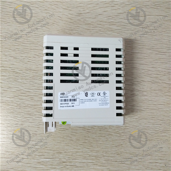
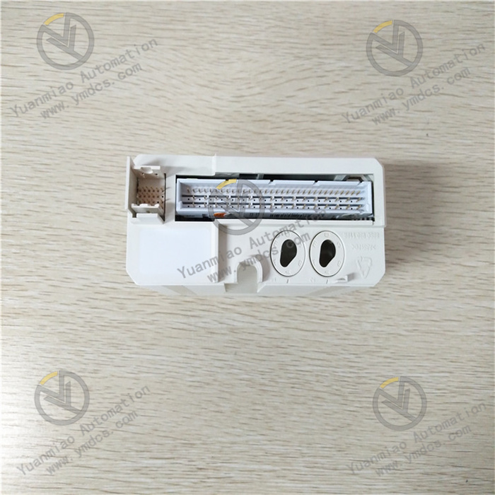
ABB DI830 3BSE013210R1
I. Overview
ABB DI811 3BSE008552R1 is a digital input module, whose core positioning is to serve as the standard field digital signal acquisition terminal for industrial automation control systems and process monitoring systems. Specifically designed for conventional signal acquisition scenarios, it can accurately collect basic field switch signals (such as equipment start/stop status signals, limit switch trigger signals, fault alarm signals, button operation signals, etc.). It stably transmits the signals to the AC 800M controller via PROFIBUS DP or industrial Ethernet bus for logical operation and analysis, providing reliable data support for real-time monitoring of industrial processes, equipment interlock protection, and production status judgment. This module is widely applicable to various general industrial scenarios including petrochemical, electric power, metallurgy, pharmaceutical, food processing, water treatment, and municipal engineering. It is especially suitable for control systems that require a moderate number of signal acquisition channels and pursue high stability and cost-effectiveness.

II. Product Features
Standard Channel Configuration: Adopting a standard channel integration design, it is equipped with 16 independent digital input channels with a reasonable layout, suitable for conventional multi-point signal acquisition requirements. While ensuring acquisition stability, it balances cabinet space utilization and system construction costs, making it an ideal choice for general industrial scenarios.
High-reliability Industrial-grade Design: Using high-quality industrial-grade components and a reinforced circuit architecture, it has passed strict Electromagnetic Compatibility (EMC) certification, environmental reliability testing, and industry safety certification. It can operate stably in harsh industrial environments with a long Mean Time Between Failures (MTBF), providing a solid guarantee for the continuity and safety of industrial production.
Accurate and Stable Signal Acquisition Capability: The 16 input channels are fully electrically isolated with an isolation voltage ≥ 500V AC, effectively avoiding signal interference between channels. It supports 24V DC wet contact input mode and is compatible with PNP/NPN signal types, which can accurately collect various basic field digital signals. The input response time is flexibly configurable (minimum ≤ 1ms), enabling quick capture of field signal changes to meet the requirements of conventional high-speed response control scenarios.
Flexible System Expansion and Compatibility: Specifically designed for ABB AC 800M series control systems, it can achieve high-speed data interaction with the controller through communication interface modules such as CI854/CI858. It supports cascade expansion of up to 32 I/O modules of the same series, with a maximum expandable I/O point count of 512, adapting to the expansion needs of industrial control systems of different scales. It is compatible with ABB Control Builder M configuration software, facilitating parameter configuration, program debugging, and operation status monitoring.
Comprehensive Online Diagnosis Function: It has a built-in perfect self-diagnosis and fault monitoring mechanism, which real-timely monitors the module power supply status, the input status of each channel, bus communication status, and external line connection status. It can accurately locate faulty channels and fault types (such as line short circuit, signal abnormality, channel open circuit, etc.), and upload fault information to the controller and upper computer system via the bus, facilitating quick handling by operation and maintenance personnel and shortening fault troubleshooting time.
Strong Environmental Adaptability and Anti-interference Capability: It has an operating temperature range of -25℃~+60℃, allowing stable operation in a wide temperature range. It boasts excellent vibration resistance (2g, 10Hz~150Hz) and shock resistance (10g, 11ms) performance. It adopts a reinforced electromagnetic shielding design and a built-in signal filtering circuit, which can effectively resist electromagnetic interference and surge interference generated by high-power equipment in industrial sites, ensuring the stability and accuracy of signal acquisition.
Convenient Operation and Maintenance Design: It supports module-level online hot swap function, allowing installation, replacement and maintenance of the module without interrupting system operation, thus greatly reducing system downtime. It is equipped with intuitive local status indicators (power, operation, communication, channel input status), enabling operation and maintenance personnel to quickly judge the overall operation status of the module and the working status of each channel, improving operation and maintenance efficiency.
- Perfect Input Protection Function: Each input channel is equipped with built-in overvoltage protection, short circuit protection and reverse polarity protection circuits. When excessive input voltage (maximum withstand voltage ≤ 35V DC), line short circuit or reverse connection of power positive and negative poles is detected, it can quickly cut off the input circuit to avoid damage to the module and field signal source equipment. After the fault is eliminated, the module can automatically resume normal acquisition function without manual reset.
III. Technical Parameters
1. Core Basic Parameters
- Product Model: ABB DI811 3BSE008552R1
- Product Type: Standard Digital Input Module
- Manufacturer: ABB Group
- Product Series: I/O Component of AC 800M Series Control System
- Core Functions: Field standard digital signal acquisition, channel status monitoring, online fault diagnosis, data uploading to controller
- Communication Method: Communicate with the controller via PROFIBUS DP/industrial Ethernet bus (matching corresponding communication interface module required)
- Applicable System: ABB AC 800M Series Industrial Automation Control System
- Application Fields: Petrochemical, electric power (thermal power, hydropower, wind power), metallurgy, steel, pharmaceutical, food processing, water treatment, municipal engineering, general manufacturing, etc.
2. Electrical Performance Parameters
- Supply Voltage: 24V DC (voltage fluctuation range: 20.4V DC ~ 28.8V DC)
- Input Type: Digital input (wet contact, PNP/NPN compatible)
- Number of Channels: 16 independent digital input channels (full isolation between channels, isolation voltage ≥ 500V AC)
- Input Voltage Range: 15V DC ~ 30V DC (effective input)
- Input Current: Normal working current of each channel ≤ 5mA DC (when powered by 24V DC)
- Input Response Time: Configurable, minimum ≤ 1ms, maximum ≤ 100ms
- Input Protection: Overvoltage protection (maximum withstand voltage ≤ 35V DC), short circuit protection, reverse polarity protection
- Fault Diagnosis Range: Channel short circuit, signal loss, power supply abnormality, communication interruption, channel open circuit
- Communication Interface: Connected to communication interface modules (e.g. CI854, CI858) via I/O bus
- Communication Protocol: Support PROFIBUS DP V1/V2 protocol
- I/O Expansion Capability: Support cascade connection of up to 32 I/O modules of the same series, with a maximum expandable I/O point count of 512
- Signal Source Type: Field switches, limit switches, buttons, proximity switches, photoelectric switches, encoders (digital signal output), travel switches and other digital equipment
3. Environmental and Physical Parameters
- Operating Temperature: -25℃~+60℃
- Storage Temperature: -40℃~+85℃
- Relative Humidity: 5%~95% RH (no condensation)
- Vibration Resistance: 2g, 10Hz~150Hz (sine wave)
- Shock Resistance: 10g, 11ms (half-sine wave)
- Protection Grade: IP20 (module itself); IP54 (when installed in standard cabinet)
- Weight: Approximately 0.8kg (module itself); 2.5kg (including transportation package)
- Installation Method: Rack-mounted installation (compatible with ABB standard I/O cabinet, compliant with IEC 60917 standard)
- Dimensions (L×W×H): 140mm × 100mm × 60mm
- Special Functions: Online hot swap, independent channel isolation, online fault diagnosis, signal filtering
IV. Working Principle
Stage 1: System Initialization and Parameter Configuration StageAfter the module establishes connection with the communication interface module (e.g. CI854, CI858) of the ABB AC 800M controller via the I/O bus and is connected to the 24V DC power supply, it automatically completes initialization startup and performs internal circuit self-test, calibration of 16 channels one by one, and communication link verification. Operation and maintenance personnel complete the configuration of input response time, fault diagnosis threshold, communication parameters and other settings through ABB Control Builder M configuration software to ensure the module is accurately compatible with field signal source equipment and the controller, meeting the response requirements of conventional signal acquisition.
Stage 2: Field Signal Acquisition and Preprocessing StageConventional field digital signals (such as equipment running status switching, limit switch triggering, button operation, etc.) are connected to the 16 independent input channels of the module via dedicated terminals. The signal filtering unit built in each channel preprocesses the original signals to filter out clutter and instantaneous jitter caused by electromagnetic interference, ensuring signal stability. Meanwhile, the high isolation voltage design between channels can effectively avoid interference between different signal sources, ensuring the accuracy of acquisition of the 16 channels.
Stage 3: Data Conversion and Bus Transmission StageThe preprocessed digital signals are converted into standard digital data by the internal logic circuit of the module and transmitted to the communication interface module via the high-speed I/O bus. The communication interface module converts the data into PROFIBUS DP protocol format and then transmits it to the AC 800M controller, providing standard data support for the controller's logical operation, equipment interlock protection decision-making and real-time monitoring. The entire data transmission process is high-speed and synchronous, ensuring the real-time performance and reliability of signal transmission.
Stage 4: Full-status Monitoring and Fault Diagnosis StageThe fault diagnosis unit real-timely monitors the module power supply status, the independent status of 16 input channels, bus communication status and external line connection status. If problems such as short circuit of a certain channel, abnormal input voltage, communication interruption or power supply fault are detected, it immediately activates the corresponding protection mechanism (such as cutting off the input of the faulty channel without affecting the normal operation of other channels), and generates detailed fault codes including fault channel number and fault type at the same time, uploading the fault information to the controller and upper computer system via the bus. After receiving the fault information, the controller prompts the fault status of the module or channel through local indicators, and the upper computer system accurately displays the details of the faulty channel, reminding operation and maintenance personnel to handle it in a timely manner.
V. Common Fault Troubleshooting
1. No Signal Acquisition/Signal Acquisition Abnormality of Partial/All Input Channels
2. Frequent Fault Alarms/False Alarms of Input Channels
3. Communication Abnormality Between Module and Controller
4. Module Fails to Start/Power Indicator Has No Response