Description
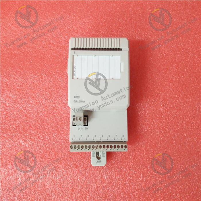
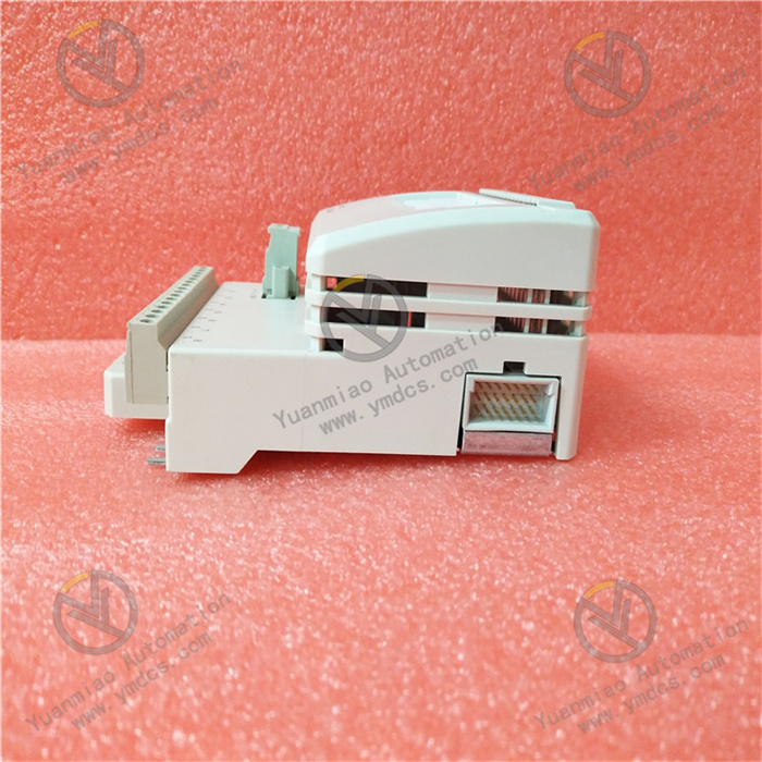
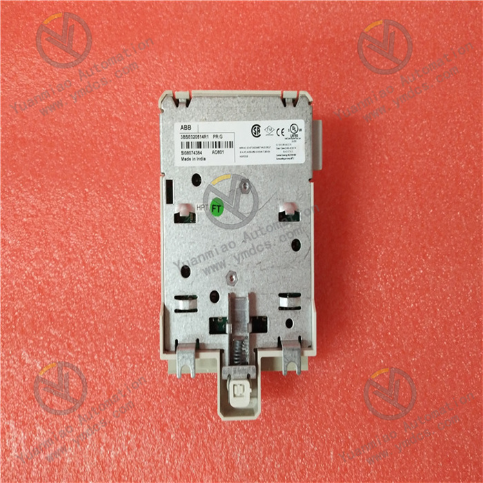
ABB AO801 3BSE020514R1
The ABB AO801 3BSE020514R1 is a single-channel high-precision analog output module belonging to the I-O module family in industrial automation control systems. It is primarily positioned as a precise digital-to-analog signal conversion and on-site actuator control unit. This module can stably convert digital commands from the controller into standard 4~20mA or 0~20mA analog signals. Equipped with comprehensive self-diagnostic functions and reliable safety protection mechanisms, it features a compact modular design and can be seamlessly integrated with mainstream automation control systems such as ABB System 800xA.
I. Product Features
1. Single-channel High-precision Output with Excellent Control Accuracy
2. Comprehensive Self-diagnostic Mechanism for Timely Fault Warning
3. Multiple Safety Protection Features for Stable and Reliable Operation
4. Compact Modular Design for Flexible Integration and Adaptation
5. Wide Environmental Adaptability for Complex Working Conditions
II. Technical Parameters
1. Basic Parameters
- Model: ABB AO801 3BSE020514R1
- Product Type: Single-channel analog output module
- Brand: ABB
- Core Functions: Converts digital signals to 4~20mA/0~20mA analog signals; supports self-diagnosis and fault protection
- Compatible Systems: ABB System 800xA
- Compatible Terminal Units: TU810, TU812 and other series terminal units
- Environmental Compliance: Complies with RoHS Directive requirements, restricting the use of hazardous substances
- Net Weight: Approximately 0.18kg
- Dimensions (W×D×H): 45mm×102mm×119mm (refer to standards for similar products)
- Warranty Period: 12 months (original factory standard warranty)
2. Electrical Parameters
- Output Channels: 1 independent channel, unipolar
- Output Signal Type: 4~20mA, 0~20mA (switchable via system configuration)
- Resolution: 14 bits
- Output Accuracy: ±0.1% FS (typical value)
- Maximum Load Resistance: 600Ω (under 4~20mA output mode)
- Protection Functions: Output short-circuit protection (current limiting); Output Status on Fault (OSP)
- Power Supply Specification: 24V DC (process power supply)
- Power Supply Fluctuation Range: ±10%
- Current Consumption: Typical value ≤ 100mA (powered by 24V DC)
- Diagnostic Functions: Power supply abnormality diagnosis; Output open-circuit diagnosis; Internal circuit fault diagnosis
3. Mechanical and Environmental Parameters
- Installation Method: Standard 35mm DIN rail mounting / modular slot mounting
- Operating Temperature: 0~+55℃
- Storage Temperature: -40~+70℃
- Relative Humidity: 5%~95% (non-condensing)
- Protection Class: IP20
- Electromagnetic Interference Resistance: Complies with EN 61000-6-2, EN 61000-6-4 EMC standards
- Vibration Resistance: Complies with IEC 60068-2-6 standard, 10~500Hz, acceleration 2g
- Shock Resistance: Complies with IEC 60068-2-27 standard, acceleration 15g, duration 11ms
III. Working Principle
The core working logic of the ABB AO801 3BSE020514R1 analog output module follows the sequence of "Power Supply → System Initialization → Signal Reception and Conversion → Analog Output and Status Monitoring → Fault Diagnosis and Protection". The specific workflow is as follows:
- If the 24V DC power supply voltage exceeds the ±10% fluctuation range, it immediately triggers a power supply abnormality alarm and reports it to the controller.
- If an output line open circuit is detected (output current is lower than the threshold and the set output value is greater than 1mA), it triggers an open-circuit fault alarm and activates the Output Status on Fault (OSP) function simultaneously, switching the output signal to the preset safe value.
- If an internal circuit fault (such as abnormal D/A conversion) is detected, it immediately cuts off the output and reports the module fault information to prevent on-site equipment malfunctions caused by incorrect signals, ensuring system operational safety.
IV. Common Fault Troubleshooting
| Fault Phenomenon | Possible Causes | Troubleshooting and Solutions |
|---|---|---|
| No module response, unable to communicate with the controller | Abnormal or interrupted 24V DC process power supply; insecure installation or poor contact between the module and terminal unit; damaged or poorly connected communication bus lines; mismatched communication protocols between the module and controller | Use a multimeter to measure the 24V DC power supply voltage to confirm it is within the 24V±10% range. If the power supply is interrupted or abnormal, check the power module and power supply lines. Re-plug the module to ensure firm contact with the terminal unit slot, and check for oxidation or looseness in the slot. Inspect the continuity of the communication bus lines, repair damaged lines, and re-fasten bus connectors. Verify that the communication protocol configuration between the module and controller is consistent (e.g., baud rate, address code, etc.). |
| No output signal or constant output value | Open-circuit or poor contact of the output line; the module does not receive digital commands from the controller; incorrect output signal type configuration; internal D/A conversion circuit fault of the module | Disconnect the module power supply, check the continuity and connector firmness of the output line, and repair open-circuit or poor contact issues. Use system diagnostic tools to check whether the module receives commands from the controller; if not, troubleshoot the communication link. Verify the output signal type configuration via the system configuration software, and reconfigure and save it if incorrect. If the above checks are all normal, an internal D/A conversion circuit fault may be the cause; contact ABB authorized after-sales service for maintenance or replacement. |
| Large output signal deviation with insufficient control precision | Uncalibrated or expired module output precision; excessive on-site electromagnetic interference; output lines placed too close to power lines; load resistance of on-site actuators exceeding the 600Ω compatible range | Re-calibrate the module output precision using dedicated calibration tools or system configuration software. Check if the module installation location is close to strong interference sources such as frequency converters and high-power motors; install a metal shield if necessary. Re-plan the wiring to ensure the distance between analog output lines and power lines is ≥ 20cm; use shielded cables for output lines and ground the shield layer at one end (ground resistance ≤ 4Ω). Test the load resistance of on-site actuators to confirm it is ≤ 600Ω; if it exceeds the range, replace the actuator with a compatible load or install a signal amplifier. |
| Continuous fault alarm triggering with OSP function activation | Output line open circuit; excessive power supply voltage fluctuation; internal circuit fault of the module | Troubleshoot the output line, repair open-circuit problems, and re-fasten line connectors. Test the stability of the power supply voltage; if the fluctuation is excessive, install a power regulator. If the power supply and lines are normal, read the specific fault code through the system diagnostic function, and contact ABB authorized after-sales service for maintenance based on the fault code; replace the module if necessary. |
| Severe module heating | Power supply voltage exceeding the allowable range; unremoved output short circuit; poor ventilation in the module installation environment with blocked heat dissipation | Immediately disconnect the module power supply, test the power supply voltage to ensure it is within the 24V±10% range. Troubleshoot the output line for short circuits and repair short-circuit hazards. Check the module installation environment to ensure good ventilation in the control cabinet and no obstacles around the module; install a cooling fan if necessary. |