Description
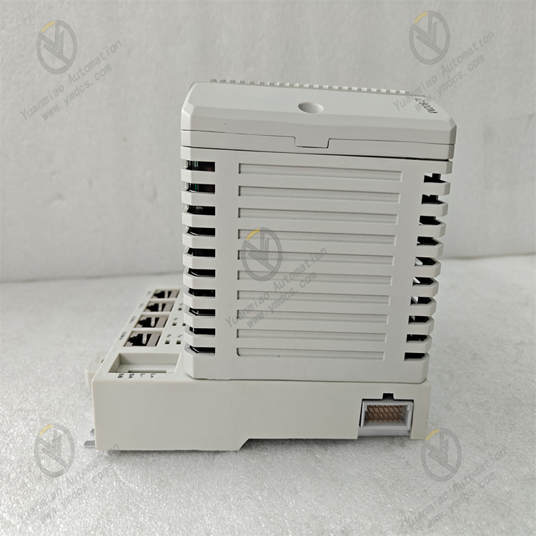
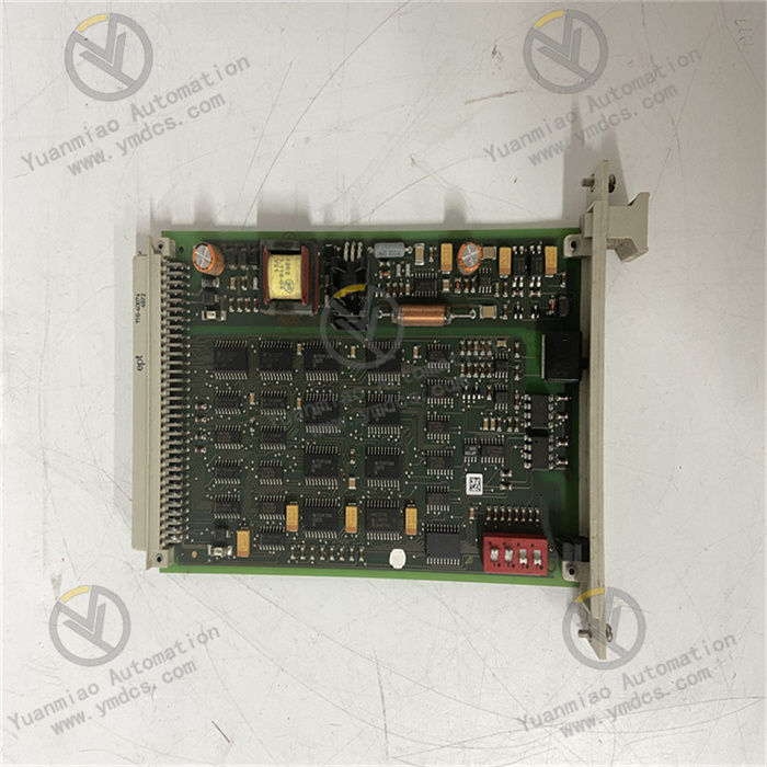
ABB PM825 3BSE010796R1
The ABB PM825 3BSE010796R1 is a distributed controller. As the core mid-range model of the AC 800M family, its core functions include executing logic control, continuous regulation, batch control and cross-device data exchange in industrial processes. It achieves seamless integration with I/O modules, intelligent instruments and third-party equipment through mainstream protocols such as Profinet and Modbus, providing a stable and efficient control solution for medium-sized industrial systems.
Designed specifically for mid-range industrial control scenarios, this controller is equipped with a high-performance 32-bit processor, supporting redundant configuration and hot-swapping. It is compatible with control systems such as ABB 800xA and Symphony Plus. With its multi-task parallel processing capability, rich protocol support, high reliability and flexible expandability, it is widely used in petrochemical plants, intelligent manufacturing production lines, municipal water treatment systems, food processing equipment, pharmaceutical production lines and other fields. It serves as the core control unit connecting on-site equipment and upper-level systems, ensuring the stable operation of industrial processes.
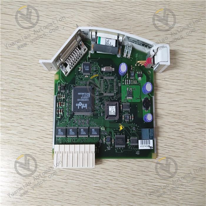
Equipped with a 32-bit PowerPC processor running at a clock speed of 400MHz, along with 256MB of RAM (for program and data storage) and 128MB of Flash storage, it supports the simultaneous operation of 1,000 function blocks and 80 control loops. It can parallel process diverse tasks such as logic control, process regulation and batch control, meeting the control requirements of medium-sized industrial systems.
The control cycle can be flexibly configured (with a minimum of 1ms), the response time for logic operations is ≤ 0.1ms per 1,000 steps, and the process regulation accuracy reaches ±0.1%. It is suitable for fast-response control scenarios, such as production line beat control and parameter closed-loop regulation.
It is compatible with IEC 61131-3 standard programming methods (Ladder Diagram (LD), Function Block Diagram (FBD), Structured Text (ST), Instruction List (IL), Sequential Function Chart (SFC)) and the ABB Control Builder M graphical programming software, facilitating the rapid development and debugging of complex control logic.
It supports hot - standby redundant configuration of dual controllers (needing to be matched with redundant modules). The active and standby controllers synchronize operating data and status in real - time through a high-speed synchronization bus, with a fault switching time of ≤ 10ms, ensuring the uninterrupted operation of critical industrial processes. The Mean Time Between Failures (MTBF) is ≥ 300,000 hours.
Adopting industrial-grade high-stability components and a sealed protection design (IP20), it operates within a temperature range of -25℃ to +60℃ and a humidity range of 5% - 95% (without condensation). Its vibration and shock resistance comply with the IEC 60068 standard, enabling long-term stable operation in harsh industrial environments such as high temperature, high humidity and heavy dust.
It has a built-in hardware watchdog and software fault-tolerant mechanism, supporting fault self-diagnosis and alarm output. It can real - time monitor the status of key components like the processor, storage and communication interfaces, and give early warnings of potential faults.
It natively supports multiple industrial communication protocols, including Profinet IO (IRT), Modbus TCP, EtherNet/IP, OPC UA and BACnet. It can be directly integrated with ABB S800 I/O modules, S900 I/O modules and third-party Profinet/Modbus devices without the need for additional protocol gateways.
It supports industrial Ethernet redundancy (MRP/MSTP) with a communication rate of 1Gbps, ensuring the stability and real - time performance of data transmission. Equipped with 2 independent Ethernet ports, it can achieve physical isolation between the control network and the information network, enhancing system security.
It is backward compatible with ABB legacy systems (such as Symphony Harmony) and seamlessly interfaces with upper-level 800xA operator stations and MES/ERP systems. It supports the upload of production data and remote monitoring, facilitating the digital transformation of the industrial sector.
It supports up to 8 local I/O bus interfaces, which can be expanded to connect S800 I/O series analog, digital and special - function modules (such as AI825, AO820 and DI810). The maximum expandable I/O channels reach 256, adapting to control requirements of different scales.
Adopting a modular design and being installed in a 19-inch 4U standard rack, it supports hot-swapping of the controller and power module. Maintenance work can be carried out without shutting down the system, reducing production downtime. The front panel is equipped with status indicators and a USB debugging interface, facilitating on-site troubleshooting and program downloading.
Remote maintenance and parameter updating are supported. Through the Control Builder M software, remote programming, parameter modification and fault diagnosis can be realized, as well as program backup and recovery, which reduces maintenance costs.
It integrates a variety of process control algorithms, including PID regulation (with automatic tuning function), feedforward control, cascade control, ratio control and batch control. It can accurately adjust process parameters such as temperature, pressure, flow rate and liquid level, ensuring the stability of the production process.
It collects equipment operating data and energy consumption parameters (voltage, current, power) in real - time, supports energy consumption monitoring and trend analysis, provides data support for optimal energy allocation, and helps reduce production energy consumption.
The core working logic of the ABB PM825 3BSE010796R1 follows the sequence of "data collection → logic operation → control output → redundant backup → communication interaction → status diagnosis". The specific process is as follows:
- Data Collection: It receives on-site sensor signals (analog/digital) collected by S800/S900 I/O modules through local I/O bus interfaces, or operating data from intelligent instruments and third-party equipment via protocols such as Profinet and Modbus, realizing the unified access of multi-source data.
Logic Operation: The high-performance PowerPC processor processes the collected data according to preset control logic (implemented through IEC 61131-3 programming). This includes complex control tasks such as logic judgment, PID regulation, batch control and equipment linkage. The operation results are fed back to the output module in real - time.
- Control Output: The processed control instructions are output to actuators (valves, motors, contactors, etc.) through I/O modules to realize operations such as equipment start-stop and parameter adjustment. It supports synchronous output of multiple channels to meet the collaborative control needs of production lines.
Redundant Backup: In the dual - controller hot - standby mode, the active and standby controllers synchronize operating data, control logic and status information in real - time through a high-speed synchronization bus. When the active controller detects a fault (such as hardware abnormality or communication interruption), it will automatically switch to the standby controller within ≤ 10ms, ensuring the uninterrupted operation of the control process.
- Communication Interaction: It conducts data exchange with upper-level 800xA operator stations and MES systems through Ethernet interfaces, uploading production data, equipment status and fault information, and receiving remote control instructions and parameter configurations. Meanwhile, it achieves real - time data communication with on-site equipment to ensure the coordinated operation of the system.
- Status Diagnosis: The module continuously monitors its own hardware status (processor, storage, power supply), the integrity of communication links and the validity of I/O channel signals. When an abnormality is detected, it triggers local alarm indicators and remote alarm notifications, and uploads fault codes to facilitate quick troubleshooting.
Install the controller in a standard 19-inch industrial control cabinet, keeping it away from strong electromagnetic interference sources such as frequency converters, high-voltage cables and high-power motors. Reserve a heat dissipation gap of no less than 20mm on both sides. The control cabinet should be equipped with ventilation or forced heat dissipation functions to prevent the ambient temperature from exceeding the range of -25℃ to +60℃.
- Confirm that the main power supply of the control cabinet is cut off. Fix the controller in the 19-inch 4U rack position and fasten it with bolts to ensure a firm installation without loosening. If a redundant system is configured, install the active and standby controllers side by side with a spacing of no less than 15mm to ensure smooth connection of the synchronization bus.
- Connect the redundant power modules (if configured) to ensure independent power supply for the active and standby power sources, improving power supply reliability. During installation, pay attention to the physical connection sequence between the controller, I/O modules and bus modules to ensure normal bus communication.
- Power Wiring: Connect to a 24V DC redundant power supply, strictly distinguish between positive and negative polarities, and fasten the wiring terminals. It is recommended to connect a 3A fuse in series at the power input end to prevent equipment damage due to short circuits. Use 2.5mm² copper core cables for power supply to ensure stable power supply.
- Communication Wiring: Connect the Ethernet interface to the industrial switch using Cat5e/Cat6 network cables, supporting Profinet IO redundant network configuration. The RS - 232 interface is used for local debugging, and communication parameters (baud rate, data bits, parity bits) should be matched during connection.
Install the ABB Control Builder M programming software. Establish a connection with the controller via USB or Ethernet interface, create a new project and add the PM825 controller model. Configure basic parameters such as communication protocols (e.g., Profinet IO, Modbus TCP), IP address and I/O module mapping relationships.
Adopt IEC 61131-3 standard programming methods (such as FBD and ST) to write control logic. Define I/O channel addresses, control parameters (such as PID proportional gain and integral time) and fault response strategies. The software supports simulation testing of the control logic.
If the redundant function is enabled, configure the IP addresses, synchronization methods and switching strategies of the active and standby controllers in the software, and activate the redundant synchronization function to ensure data consistency between the active and standby controllers.
- Before the first power-on, verify the correctness of wiring, and the consistency between the controller model and configuration parameters to ensure there are no issues such as short circuits or reverse connections. Use a multimeter to test the power supply voltage to ensure it fluctuates within the range of 24V DC ± 10%.
After power-on, observe the status indicators on the front panel of the controller. A steady power indicator (PWR) and a blinking run indicator (RUN) indicate normal operation. If the fault indicator (FAULT) stays on, use the software to troubleshoot the cause of the fault.
- Function Testing: Force the output of control instructions through the software and observe whether the actuator actions meet expectations. Input standard signals to test PID regulation accuracy and verify control response time and stability. Test the redundant switching function by simulating a fault in the active controller and check if the standby controller can take over control quickly.
- Communication Testing: Verify the communication connections between the controller and the 800xA operator station, I/O modules and third-party Profinet devices to ensure real-time data transmission without packet loss. Test the functions of remote parameter modification and program downloading to ensure normal remote maintenance.
Monitor the operating status of the controller in real - time through the 800xA operator station or local debugging software:
- Normal Status: Stable power supply, blinking run indicator, no fault alarms, control parameters maintained within a reasonable range, and normal synchronization of the redundant system.
- Fault Status: The fault indicator stays on or blinks, and the operator station displays fault codes (such as hardware faults, communication faults, redundant switching faults). Troubleshooting should be conducted by combining the fault codes and wiring status.
- Monthly Maintenance: Clean dust on the controller surface and interfaces with dry compressed air. Check the installation firmness and whether the wiring terminals are loose or oxidized. View operation logs and fault records through the software to ensure no abnormalities. Inspect the synchronization status of the redundant system to ensure data consistency between the active and standby controllers.
- Half-yearly Maintenance: Conduct a comprehensive inspection of power and communication cables for insulation damage or aging, and check the reliability of the shielding layer grounding. Back up control programs and configuration parameters and store them in a safe location. Test the redundant switching function and fault self-diagnosis capability to ensure system reliability.
- Annual Maintenance: Inspect internal components of the controller for signs of aging, such as swollen capacitors or loose interfaces. Upgrade the controller firmware and programming software to the latest stable versions (back up programs in advance). If the controller experiences problems like operation lag or frequent faults, replace the spare parts with original ones in a timely manner.
![]()