Description
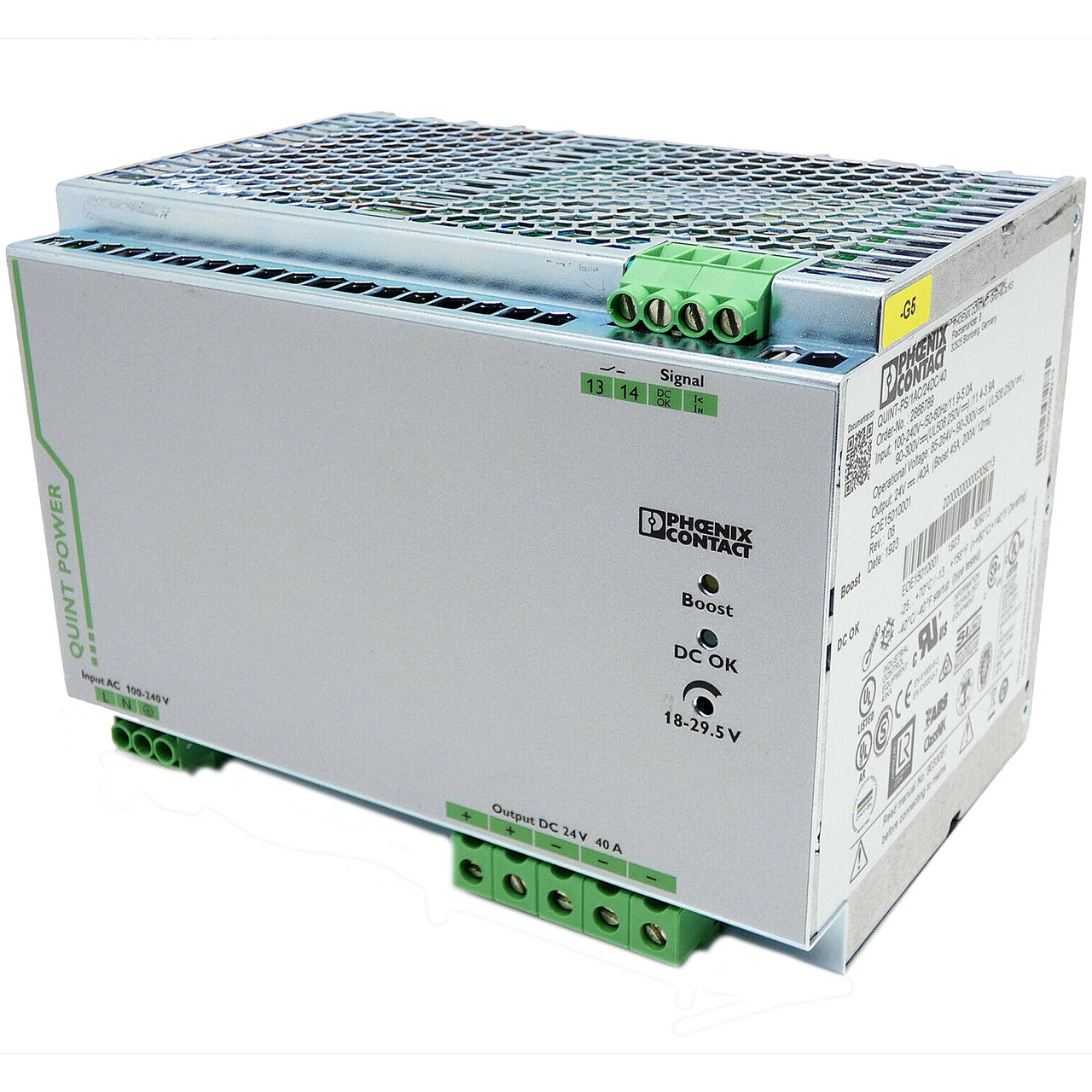
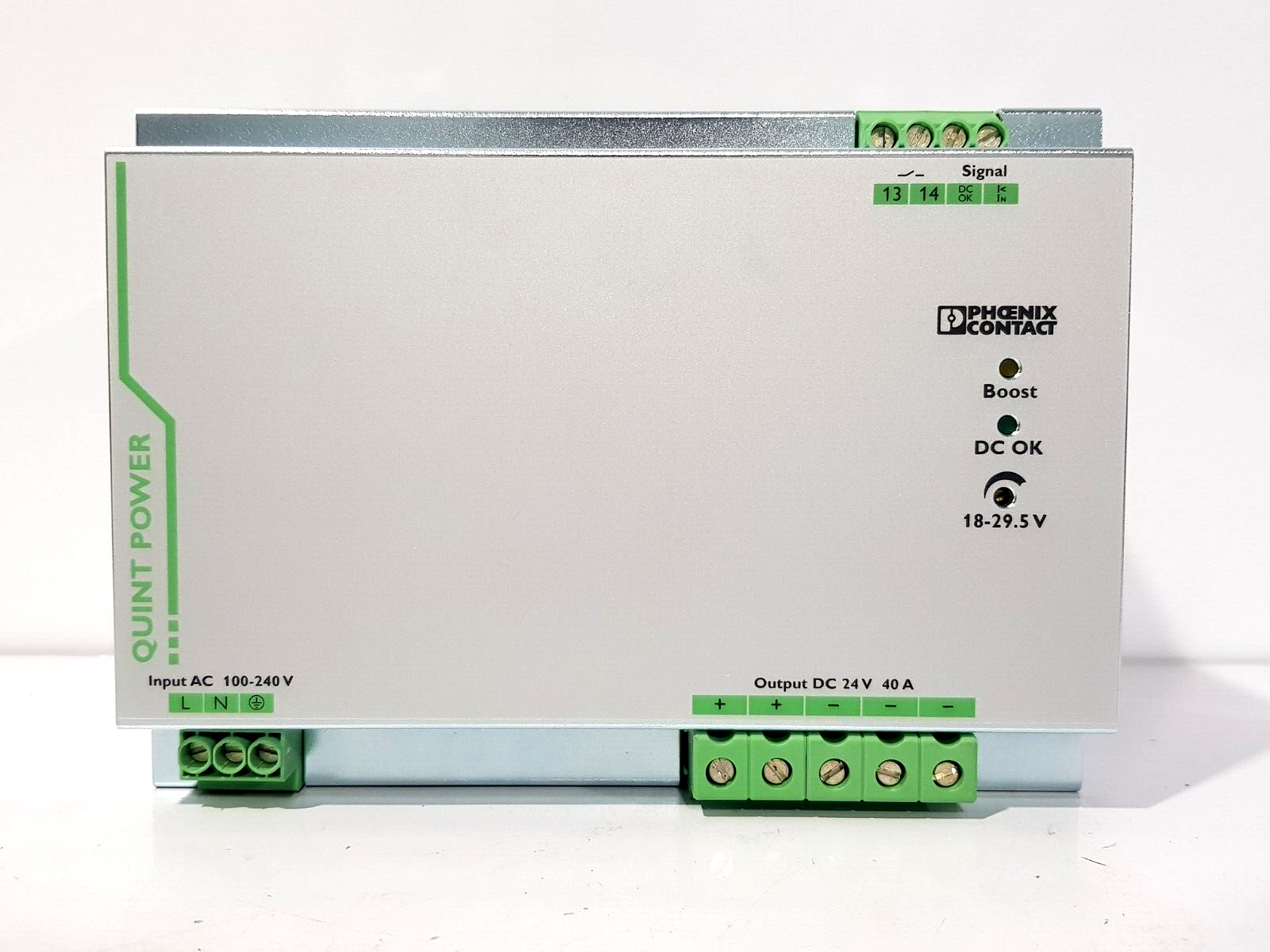
Phoenix QUINT-PS/1AC/24DC/40
I. Product Overview
- Model: QUINT-PS/1AC/24DC/40 (Part No.: 2866789)
- Version: Standard Version
- Global Part Number: 2866789
- Product Series: Phoenix Contact QUINT POWER Series Industrial DIN Rail Power Supply
- Product Category: Single-phase AC-to-DC High-performance Regulated Switching Power Supply (Industrial Redundancy-compatible Type)
- Country of Origin: Germany
Core Functions
This unit is a main industrial power supply of the Phoenix Contact QUINT POWER series, designed for high-reliability power supply in harsh industrial environments.It mainly performs single-phase AC to 24V DC regulated output, system power protection, and redundant coordination.
Adopting advanced switching power supply topology and SFB (Selective Fuse Breaking) technology, it provides a static boost capacity of up to 45 A, reliably driving high-inrush loads such as motors and contactors.It features a mains hold-up time of >35 ms, ensuring system operation during short power interruptions.Comprehensive protection is integrated: overvoltage, overcurrent, short-circuit, and overtemperature protection.A DC OK relay signal supports fault alarming in conjunction with PLCs.
The unit supports parallel redundancy and capacity expansion; with QUINT ORING modules, it enables bumpless switchover.Output voltage accuracy is ±1%, ripple <50 mVpp, ensuring stable power for control signals and loads without additional filtering modules.
Application Scenarios
Widely used in automotive manufacturing, metallurgy, petrochemical, power generation, rail transit, water treatment, and automated production lines.Suitable for industrial loads including PLCs, DCS, remote I/O, HMIs, servo drives, and solenoid valves.
Especially ideal for critical control systems with extremely high power reliability requirements, such as emergency stop circuits, safety PLC systems, UPS front ends in data centers, and offshore platform power supply.It can be seamlessly integrated into Phoenix Contact and third-party redundant architectures, meeting demands for 24/7 continuous operation, strong electromagnetic interference immunity, and stable performance in wide temperature ranges.
II. Technical Specifications
| Parameter Category | Details |
|---|---|
| Electrical Specifications | Input: 85–264 VAC single-phase (45–65 Hz), compatible with 90–300 VDC inputOutput: 24 VDC regulated, rated current 40 A; static Boost 45 A; SFB peak current 215 A (15 ms)Output adjustable range: 18–29.5 VDCEfficiency: >92% at rated load with 230 VAC inputIsolation voltage: Input-output 4 kV AC (type test), 2 kV AC (routine test)Ripple and noise: <50 mVppProtection: Overvoltage, overcurrent, short-circuit, overtemperature, reverse polarity protection; DC OK relay output (max. 1 A) |
| Physical Specifications | Mounting: Standard NS 35 DIN rail, width 180 mm, height 130 mm, depth 125 mmNet Weight: approx. 3.8 kgProtection Degree: IP20 (must be installed in a control cabinet)Mounting Method: DIN 35 rail clip with additional screw fastening, screw terminal connection |
| Environmental Adaptability | Operating temperature: -25℃ to +70℃ (derated at high temperatures per curve)Storage temperature: -40℃ to +85℃Relative humidity: 5%–95% (non-condensing)Immunity / Surge: Complies with IEC 61000-6-2 industrial EMC standard, built-in surge suppression devicesMTBF: >900,000 hours at 25℃ |
III. Installation and Maintenance Guide
Pre-installation Requirements
- Anti-static: Wear a grounded anti-static wristband during operation. Do not touch terminals or internal PCB with bare hands. Keep the power supply in original sealed packaging before installation.
- Environment: Install in a dust-free, well-ventilated control cabinet, away from inverters, high-voltage cables, and high-power thyristors. Equip the cabinet with fans or air conditioning to maintain -25℃ to +70℃. Prevent direct contact with dust, oil mist, and condensation.
- Wiring rules: Strictly distinguish L/N/PE and +24V/0V according to terminal markings. Route power cables and signal cables in separate ducts. PE ground terminals must be securely connected to the system ground busbar. SFB function requires specified fuse types. For parallel redundancy, ORING decoupling modules must be used; direct short-circuiting of outputs is prohibited.
- Parameter setting: Adjust output voltage via potentiometer if needed. Verify DC OK relay wiring. Redundant systems must use uniform firmware versions and tested switchover functions. Check for short circuits and reversed wiring before power-on.
Routine Inspection
- Indicator lights: Observe the green power run LED (steady on) and red fault LED (off). Confirm normal DC OK relay status. For abnormalities, first check input voltage, load, and cooling.
- Temperature and air ducts: Ensure the housing is not abnormally hot. Keep cabinet filters unblocked and fans quiet. Maintain clear heat dissipation paths.
- Wiring and terminals: Inspect input/output terminals and PE ground screws for looseness, oxidation, or burning. Check cables for aging or cracking.
- Operating parameters: Measure output voltage with a multimeter (24V±1%). Record load current to avoid long-term overloading. Check load balancing in redundant systems.
Periodic Maintenance
- Every 6 months: Clean cabinet filters and dust from the power supply housing; retighten all wiring terminals; test DC OK alarm and mains hold-up function; verify parallel redundancy communication links.
- Annually: Measure output accuracy, ripple, and regulation range with professional instruments; back up system configuration; inspect DC OK relay contacts; evaluate fan aging and replace if necessary; establish maintenance records.
- Every 2 years: Perform comprehensive tests of insulation resistance and surge suppression performance; verify SFB breaking current rating; evaluate firmware upgrades (after compatibility testing); assess replacement intervals for units operating in high-dust / high-corrosion environments.
IV. Common Faults and Troubleshooting
| Fault Symptom | Possible Causes | Troubleshooting & Solutions |
|---|---|---|
| No output, indicator lights off | 1. Missing or abnormal input power2. Blown fuse3. Loose terminals or incorrect wiring4. Overtemperature protection lockout | 1. Measure input voltage and restore to 85–264 VAC2. Power off, check internal slow-blow fuse, replace with identical type3. Verify wiring and retighten terminals4. Allow cooling, then power cycle |
| Abnormal or unstable output voltage | 1. Overload or short-circuited load2. Misadjusted voltage potentiometer3. Severe mains voltage fluctuation4. Excessive ripple due to interference | 1. Reduce load or locate short circuit2. Reset to 24V nominal and lock3. Install input reactor4. Improve grounding and separate power/signal cables |
| Abnormal or false DC OK alarm | 1. Loose DC OK relay wiring2. Output voltage threshold drift3. Internal detection circuit failure | 1. Tighten DC OK connections2. Recalibrate output voltage3. Replace faulty module |
| Frequent overtemperature protection | 1. Excessive ambient temperature2. Blocked heat dissipation ducts3. Long-term over-power operation4. Faulty cooling fan | 1. Improve cabinet cooling2. Remove dust and debris3. Balance load within rated capacity4. Replace defective fan |