Description
ABB 3BHE023126R0010
ABB 3BHE023126R0010 is a core component of industrial automation control systems, mainly applied in the control and monitoring systems of critical equipment in large-scale industrial scenarios such as power energy, petrochemicals, and metallurgical manufacturing. As an important functional module in the system, it undertakes core tasks including signal processing, command transmission, and status monitoring. Through precise signal interaction and stable operation performance, it ensures the efficient coordination and safe operation of backend host equipment (such as generator sets, large frequency converters, and industrial boilers). Adopting an industrial-grade high-reliability design, it features excellent anti-interference capability, wide environmental adaptability, and comprehensive diagnostic functions. It can be seamlessly integrated with ABB series controllers, terminal units, and other peripherals, serving as a key supporting component for achieving precise control and efficient operation and maintenance under complex industrial working conditions.
I. Product Features
1. High-reliability Industrial-grade Design
2. Precise Signal Processing and Interaction Capability
3. Comprehensive Safety Protection and Isolation Design
4. Full Lifecycle Status Monitoring and Diagnostics
5. Modular Architecture with Excellent Compatibility and Scalability
6. Wide Environmental Adaptability for Complex Working Conditions
II. Technical Specifications
1. Basic Parameters
- Model: ABB 3BHE023126R0010
- Product Type: Industrial Control Core Component/Functional Module
- Brand: ABB
- Product Series: Industrial Automation Control Series
- Application Fields: Power Energy (thermal power generation, hydropower generation, new energy power generation), Petrochemicals, Metallurgical Manufacturing, Large Industrial Equipment Control
- Compatible Systems: ABB 800xA Distributed Control System and other mainstream industrial automation systems
- Compatible Terminal Units: ABB S800 I/O series terminal units (such as TU 810, TU 812, etc.) and compatible industrial terminals
- Mounting Method: DIN Rail Mounting (Compliant with EN 50022 Standard)
- Net Weight: Approximately 0.45kg
- Warranty Period: 12 Months
- RoHS Compliance: Conforms to EU Directive 2011/65/EU (RoHS 2.0)
- WEEE Category: Category 5 (Small Electronic Equipment)
2. Electrical Parameters
- Supply Voltage: 24V DC±10%
- Power Consumption: Typical value ≤8W (Full-load operating condition)
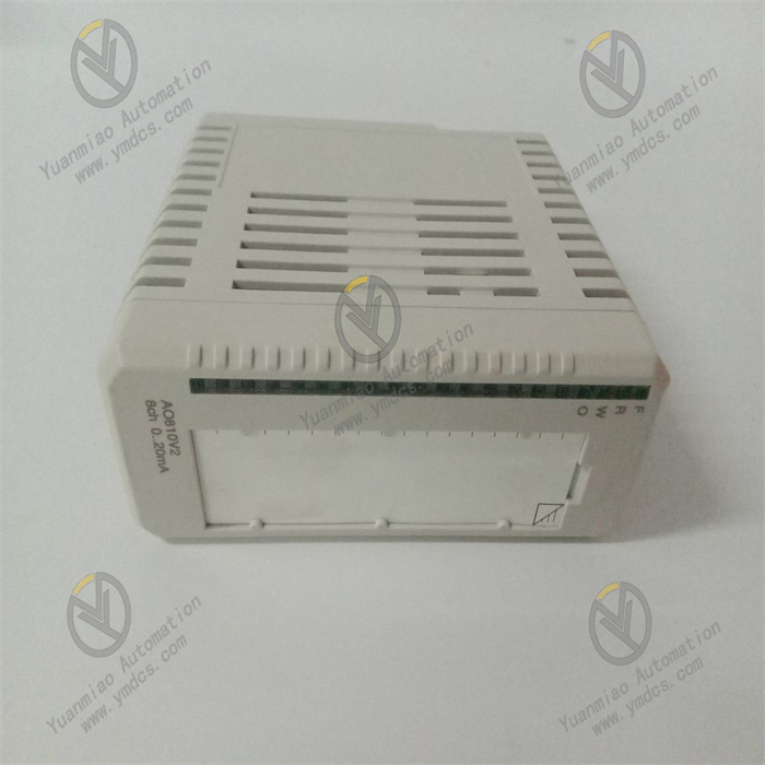
- Input/Output Signal Types: Supports standard industrial signals such as 4-20mA current signals and 0-10V voltage signals
- Signal Processing Accuracy: ±0.1% FS
- Isolation Class: Full isolation between input and output, input and power supply, and between channels, rated isolation voltage 250V AC (Continuous)
- Communication Protocol: Supports industrial standard communication protocols such as HART 7.0 and Modbus
- Response Time: ≤15ms (Signal processing and transmission)
- Output Current Limit: ≤25mA per channel (Transmitter power supply)
3. Mechanical & Environmental Parameters
- Dimensions (W×H×D): 48mm×125mm×108mm
- Operating Temperature: -25℃~+70℃
- Storage Temperature: -40℃~+85℃
- Relative Humidity: 5%~95%RH (Non-condensing)
- Electromagnetic Immunity: Compliant with EN 55011 Group 1 Class A, EN 61000-4-2 (ESD), EN 61000-4-3 (Radiated Immunity), EN 61000-4-4 (Electrical Fast Transient), EN 61000-4-5 (Surge) standards
- Vibration Resistance: Compliant with IEC 60068-2-6 standard, 10-150Hz, acceleration 5g
- Shock Resistance: Compliant with IEC 60068-2-27 standard, acceleration 15g, duration 11ms
- Protection Class: IP20 (Front-end protection after DIN rail mounting)
III. Working Principle
The core working logic of ABB 3BHE023126R0010 follows the sequence of "Signal Access - Power Supply Guarantee - Signal Processing - Command Transmission - Status Monitoring - Diagnostic Feedback". The specific workflow is as follows:
- Signal Access and Power Supply Guarantee: Analog or digital signals output by front-end industrial equipment such as sensors and actuators are connected to the product interface through dedicated terminals. The product provides standard working power for itself and front-end peripherals requiring power supply (such as two-wire sensors) through its built-in stable power supply circuit. Meanwhile, it ensures the safety and stability of the power supply circuit through overcurrent and overvoltage protection mechanisms.
- Signal Processing and Conditioning: The accessed signals first pass through the internal filter circuit to remove electromagnetic interference and noise in the industrial site, and then are amplified, linearized, or format-converted through the signal conditioning circuit, converting non-standard signals into standard signals recognizable by the controller. Electrical isolation between input signals and backend processing circuits is achieved through isolation circuits to prevent interference signals from affecting processing accuracy and system safety.
- Command Interaction and Transmission: The processed signals are transmitted to the ABB controller through the standard communication bus, providing accurate data support for the controller's decision-making and analysis. At the same time, it receives control commands issued by the controller, parses them through the internal logic circuit, converts them into signals executable by terminal equipment, and transmits them to the corresponding actuators to achieve precise control of industrial equipment.
- Status Monitoring and Diagnostic Feedback: The product real-time monitors its own power supply voltage, internal circuit working status, on-off status of the signal transmission link, and connection status of front-end/backend equipment. When abnormalities such as signal overrange, circuit failure, loose connection, overheating, or overcurrent are detected, it immediately activates the diagnostic mechanism, generates detailed fault codes including fault location and fault type, and feeds them back to the control system through the communication link. At the same time, it triggers local alarm indicators (power alarm, signal alarm, fault alarm) to remind maintenance personnel to handle the problem in a timely manner.
IV. Common Troubleshooting
| Fault Phenomenon | Possible Causes | Troubleshooting and Solutions |
|---|---|---|
| Power indicator not lit, product unresponsive | Abnormal power supply (power failure, voltage out of ±10% range), loose or reversed polarity of power terminal wiring, poor connection between product and terminal unit/controller, internal power circuit failure | Use a multimeter to measure the voltage at the power terminals to ensure it meets the 24V DC±10% requirement; check if the power terminal wiring is firm and verify the correctness of polarity connection; inspect the connection interface between the product and the terminal unit/controller to ensure it is properly seated and firm, re-plug to confirm reliable connection; if the above checks are all normal but the product remains unresponsive, internal power circuit failure may be the cause—contact ABB authorized after-sales service for repair or replacement. |
| Abnormal signal transmission, large data deviation or data loss | Loose or poor connection of signal cables, poor or ungrounded shielded cables, strong external electromagnetic interference, signal conditioning circuit failure, loss of calibration parameters, failure of front-end sensors/backend actuators | Re-tighten the signal cable terminals and check for broken or damaged cables; replace damaged cables; confirm that shielded cables are used for signal transmission and the shielding layer is grounded at one end (grounding at the controller end is recommended); keep away from strong interference sources such as frequency converters and high-voltage cables; install a metal shield if necessary; calibrate the product's precision with a standard signal source and restore calibration parameters; connect the front-end sensors/backend actuators to other normal channels for testing to determine if there is equipment failure; repair or replace faulty equipment; if the above operations are ineffective, internal signal conditioning circuit failure may be the cause—contact after-sales service for repair. |
| Communication failure, unable to interact with controller/peripherals | Incorrect or broken communication cable wiring, mismatched communication parameters (address, baud rate, protocol type), communication interface failure, communication module failure of controller/peripherals | Check if the communication cable wiring is correct and verify that the wire sequence complies with protocol requirements; check for broken or poor connection of cables; replace the communication cable for testing; confirm that the communication parameters (address, baud rate, protocol type) of the product and the controller are consistent; reconfigure through the control system if mismatched; use a multimeter to measure the pin voltage of the communication interface to determine if there is an interface failure; contact after-sales service for repair if faulty; connect the product to other normal controllers for testing to rule out communication module failure of the controller. |
| Abnormal signal or no signal in specific channels | Loose or broken wiring of the channel, failure of sensors/actuators corresponding to the channel, internal circuit damage of the channel, incorrect calibration parameters of the channel | Re-tighten the signal wiring of the channel and check for broken cables; connect the sensors/actuators corresponding to the channel to other normal channels for testing to determine if there is equipment failure; repair or replace faulty equipment; verify the calibration parameters of the channel and re-calibrate and save the parameters; if the above checks are all normal, internal circuit damage of the channel may be the cause—contact ABB authorized after-sales service for repair. |
| Frequent alarm triggering, repeated appearance of fault codes | Excessive fluctuation of supply voltage, continuous strong external electromagnetic interference, product installation ambient temperature out of range, compatibility abnormality between product and associated equipment, internal logic circuit failure | Measure the supply voltage; install a voltage stabilizer at the front end if the fluctuation is excessive; strengthen electromagnetic interference protection, optimize cable layout, keep away from strong interference sources, and replace with high-quality shielded cables; check the product installation ambient temperature; take cooling or heat preservation measures if it exceeds the -25℃~+70℃ range; confirm the model and protocol compatibility between the product and associated equipment; replace incompatible equipment; if the above measures are ineffective, internal logic circuit failure may be the cause—contact after-sales service for repair or replacement. |