Description
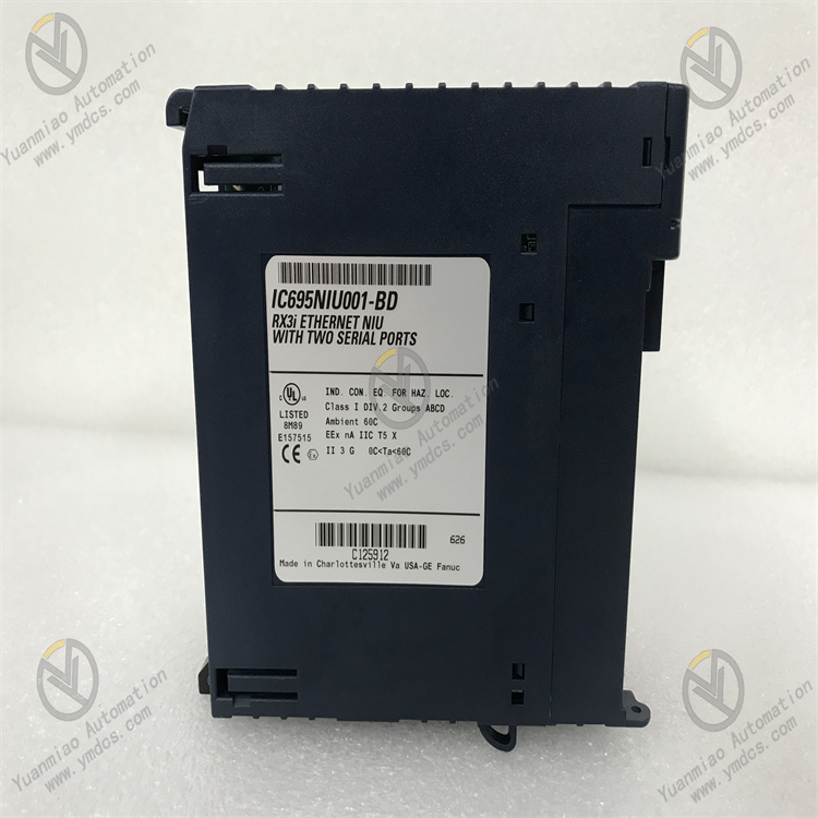
GE IC695NIU001
GE IC695NIU001 is an Ethernet Interface Unit (NIU) whose core function is to achieve high-speed data exchange between industrial control systems, field devices and upper-level systems, supporting multi-protocol compatibility and remote I/O access. As the "hub" of industrial network communication, this module is compatible with the RX3i PCI and 90-30 serial backplanes, integrating dual Ethernet ports and dual serial ports. It supports various industrial protocols such as EtherNet/IP, Modbus TCP and SNP. With a 1Gbps adaptive communication rate, redundant network design and industrial-grade anti-interference capability, it is widely used in scenarios like automotive manufacturing, energy power generation, food and beverage processing, and building automation. It serves as a key communication component connecting distributed devices and centralized control systems.
It supports 10/100/1000 Mbps adaptive Ethernet communication, with a data transmission rate of up to 1 Gbps in full-duplex mode, meeting the requirements of real-time control scenarios such as high-speed sorting and precision assembly. Meanwhile, it is compatible with multiple industrial protocols including TCP/IP, UDP, Modbus TCP, EtherNet/IP and SNP, enabling seamless integration with third-party PLC, HMI and SCADA systems.
Integrated with dual serial ports (RS-232 and RS-485), it supports Modbus master-slave mode and serial I/O communication. It can directly connect to traditional serial devices such as sensors and actuators without additional protocol conversion modules, thus protecting existing equipment investments.
The dual Ethernet ports support redundant network topology, which can be configured as link redundancy or IP redundancy mode to ensure uninterrupted communication in case of single-point network failure. It supports Ethernet Global Data (EGD) exchange, realizing data sharing and coordinated control among multiple controllers, and is suitable for distributed control systems.
It supports remote access to RX3i and 90-30 series I/O systems, enabling remote monitoring, parameter configuration and fault diagnosis of field devices via Ethernet, which reduces on-site operation and maintenance costs.
Adopting conductive/magnetic shielding design and hardware filter circuit, it can effectively resist high-frequency electromagnetic interference in industrial sites and pass strict anti-interference tests. It has an operating temperature range of -40℃~+70℃, humidity of 5%-95% (non-condensing) and protection class of IP20, adapting to harsh operating environments such as high temperature and high humidity.
Equipped with a battery-powered real-time clock (with a battery life of up to 5 years), it accurately records timestamp information, supports time-sensitive applications such as log recording and scheduled tasks, ensuring the accuracy of data traceability.
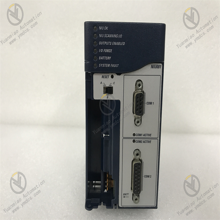
The module surface is equipped with multiple sets of status indicators (power light, Ethernet port light, serial port light, fault light, I/O force light), which intuitively feedback power supply status, communication status and fault information. For example, when the "I/O FORCE" light is on, it indicates the existence of forced variables, facilitating quick problem location.
It supports online firmware upgrade and remote diagnosis. Through GE's special configuration software, users can read communication status, fault codes and data transmission statistics, and configure EGD communication timeout parameters to ensure stable system operation.
It is seamlessly compatible with the RX3i PCI backplane and 90-30 serial backplane. The single-slot design saves installation space, and it can be directly integrated into existing RX3i or 90-30 series control systems without modifying the rack structure.
It supports redundant controller configuration and can serve as a communication interface unit of redundant systems, meeting the requirements of SIL safety levels and adapting to key industrial control scenarios.
The core working logic of IC695NIU001 is "Protocol Parsing → Data Forwarding → Status Feedback → Fault Diagnosis", and the specific process is as follows:
- Protocol Parsing and Data Reception: Signals from field devices (sensors, actuators) or upper-level systems (SCADA, HMI) are connected to the module via Ethernet or serial ports. The built-in protocol stack of the module parses different types of communication protocols and converts heterogeneous data into a unified format.
Data Forwarding and Exchange: It communicates with the RX3i controller or 90-30 system through the backplane bus, realizing remote I/O data collection and control command issuance. It supports EGD global data exchange, synchronizing controller data to other devices or forwarding external commands to field actuators.
- Status Monitoring and Feedback: It real-time monitors communication link status, port connection status and data transmission integrity, and intuitively feeds back through status indicators. It uploads communication statistics (such as transmission rate, number of error frames) and fault information to the controller, supporting remote query.
- Fault Handling and Fault Tolerance: When detecting network interruption, port failure or power supply abnormality, it triggers fault alarm and records fault codes; redundant ports switch automatically to ensure communication continuity; default output status (last-value hold or default reset) can be configured for data transmission timeout.
Installation Environment: Install in an industrial control cabinet, away from strong electromagnetic interference sources such as frequency converters and power cables. Reserve a heat dissipation gap of ≥10mm on both sides. If the ambient temperature of the control cabinet exceeds 60℃, it is recommended to install a cooling fan.
Mechanical Installation:
- Confirm that the power supply of the control cabinet is cut off. Install the module on the guide rail through the DIN rail fixing seat, or insert it into the corresponding slot of the RX3i/90-30 rack to ensure firm installation without loosening. When installing multiple modules, keep a spacing of ≥15mm between modules to avoid heat accumulation and signal interference.
- Check whether the module connectors and ports are intact without pin bending or oxidation to ensure reliable wiring.
Wiring Specifications:
- Power Wiring: Connect to 24VDC power supply, with positive and negative poles corresponding to the "V+" and "GND" terminals of the module. Use 1.5mm² copper core shielded wire for the power cable, with the shield layer grounded at one end (grounding resistance ≤4Ω).
- Ethernet Wiring: Connect to an industrial Ethernet switch or upper-level system through the RJ45 interface, using shielded Cat5e/Cat6 cables. For redundant configuration, connect to dual switches.
- Serial Wiring: The RS-232 port is used for short-distance communication (≤15m), and the RS-485 port supports long-distance communication (≤1200m). Use shielded wires grounded at one end, and avoid parallel wiring with power lines.
Hardware Configuration:
- Port Configuration: Select the working mode (full-duplex/half-duplex) of the Ethernet port according to communication requirements. Set the RS-485 terminal resistor through the DIP switch (enable for long-distance communication).
- Backplane Adaptation: Confirm that the module is compatible with the rack backplane (RX3i PCI or 90-30 serial) to ensure normal backplane power supply.
Software Configuration (GE Proficy Machine Edition):
- Install Proficy Machine Edition software, create a new RX3i project and add the IC695NIU001 module. Configure network parameters such as IP address and subnet mask to ensure consistency with the system network segment.
- Protocol Configuration: Select communication protocols (such as Modbus TCP master/slave, EtherNet/IP), set EGD data exchange parameters (production cycle, timeout time. It is recommended that timeout time = 3×production cycle + 2ms).
- Redundant Configuration: Enable dual Ethernet port redundancy, set the switchover conditions between the primary and backup ports, download the configuration file to the module, and restart to take effect.
Commissioning and Testing:
- Communication Test: Verify the network connectivity of the module through the ping command; test serial port communication using Modbus debugging tools to ensure normal data transmission and reception.
- EGD Exchange Test: Configure the EGD producer/consumer relationship between the controller and the module, monitor data synchronization delay to ensure it is ≤10ms.
- Fault Simulation Test: Disconnect the Ethernet cable to verify the automatic switchover function of redundant ports; simulate sensor disconnection to check whether the module feeds back fault information.
Status Monitoring: Monitor the operation status in real time through module status indicators and software:
- Normal Status: PWR is always on, LINK/ACT is flashing (data transmission), COM ports are flashing as needed, FAULT is off.
- Fault Status: FAULT is always on or flashing. Judge the fault type (such as low battery, network interruption) based on the combination of indicators, and read detailed fault codes through software.
Regular Maintenance:
- Monthly: Clean dust on the module surface and connector contacts with dry compressed air; check whether the wiring terminals are loose and the shielded wires are reliably grounded; view fault records and battery status through software.
- Every 6 Months: Test the reliability of redundant switchover and the stability of communication rate; calibrate the real-time clock to ensure accurate timestamps; back up configuration files and communication logs.
- Annually: Check whether the internal capacitors and connectors of the module are aging (such as capacitor bulging, contact oxidation); update the module firmware to the latest version to optimize communication performance.
Notes:
- Wiring and configuration modifications must be performed with the power off. Do not hot-swap the module or modify the wiring to avoid short circuits or module damage.
- Ensure stable power supply during firmware upgrade to avoid module failure caused by upgrade interruption. For redundant configuration, use switches of the same brand and rate to ensure switchover reliability.
- For modules idle for a long time (more than 6 months), conduct continuity tests and communication verification before commissioning to ensure no abnormalities before connecting to the system.
![]()