Description
ABB BC810K01 3BSE031154R1
I. Overview
ABB BC810K01 3BSE031154R1 is a CEX bus interconnection unit kit, with its core positioning as a universal CEX bus communication interconnection kit for single-link/redundant architecture. Designed specifically for high-speed data interaction between devices in industrial scenarios, this kit builds a stable CEX bus link through the combination of standardized components, realizing data encoding, decoding, transmission and exchange between different modules, controllers and terminal devices. It is a key communication component for constructing high-reliability Distributed Control Systems (DCS).
II. Kit Composition
The BC810K01 3BSE031154R1 is a standardized integrated kit, and each component cooperates to realize the complete CEX bus interconnection function. The specific composition is as follows, which is suitable for single-link construction and redundant expansion requirements:
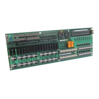
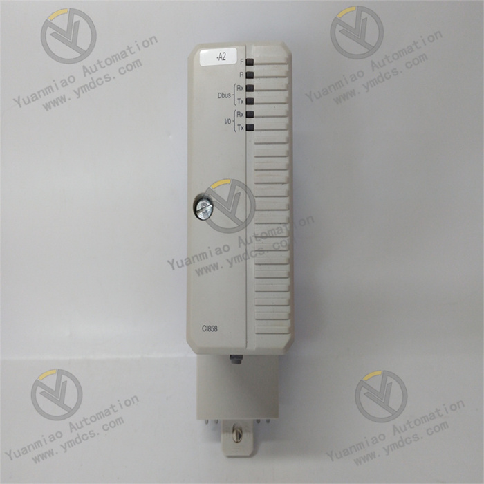
BC810 Interconnection Unit: 1 core unit, consisting of a TP857 backplane and a power/logic board. It is the core component for signal reception, conversion, encoding/decoding and bus interconnection transmission. The logic board integrates a +3.3V voltage converter, a CEX bus interconnection driver and cable connectors.
TP857 Backplane: 1 adapter backplane with a width of 60mm. It integrates CEX bus connectors and external power interfaces, and is equipped with external power voting diodes and fuses. It provides an installation carrier and power supply circuit protection for the interconnection unit, and is grounded with 35mm DIN rails through the metal parts of the housing to enhance anti-interference capability.
- TB850 CEX Bus Terminator: 1 terminal component, installed at one end of the CEX bus. It is used to suppress signal reflection, stabilize bus waveforms, avoid communication abnormalities caused by signal interference during high-frequency data transmission, and ensure the integrity of data transmission.
III. Product Features
Multi-protocol Compatibility and Global Interconnection: Supports multiple mainstream industrial communication protocols such as PROFIBUS, Modbus and CEX-Bus. It can realize data interaction and transmission exchange between different buses and devices, adapting to the heterogeneous device integration requirements of complex automation systems.
Redundant Expansion and High Reliability: Supports the configuration of redundant communication interface units, and can be flexibly expanded into a dual-link redundant architecture, effectively avoiding communication interruption caused by single-link faults. Combined with the circuit protection components integrated on the backplane, it significantly improves the communication stability and uninterrupted operation capability of the system.
Hot-swapping and Online Maintenance: Supports hot-swapping function and online CPU replacement. In the redundant system configuration, the CPU backplane can be replaced online without interfering with CEX bus communication traffic, minimizing maintenance downtime and ensuring production continuity and operation & maintenance efficiency.
Modular Design for Easy Operation & Maintenance: The interconnection unit adopts a split structure of "backplane + power/logic board". The components have clear division of labor and simple structure, facilitating separate inspection, repair and replacement of faulty parts without replacing the entire kit, thus greatly reducing operation & maintenance costs and cycles.
Wide Working Condition Adaptability: Adopts industrial-grade component packaging, with an operating temperature range of -20℃ to +60℃, and supports stable 24V DC power supply. It can withstand harsh industrial environments with heavy dust, large temperature differences and strong electromagnetic interference, adapting to various complex application scenarios.
- High-speed Real-time Data Transmission: Has high-speed data transmission capability, can quickly complete signal encoding/decoding and data interaction, meets the response requirements of industrial automation systems for real-time monitoring and precise control, and ensures the real-time performance and accuracy of data transmission.
IV. Technical Parameters
| Parameter Name | Specification |
|---|---|
| Product Model | ABB BC810K01 3BSE031154R1 |
| Product Type | CEX Bus Interconnection Unit Kit |
| Product Series | ABB Advant 800xA Series |
| Compatible Protocols | PROFIBUS, Modbus, CEX-Bus, etc. |
| Power Supply | 24V DC |
| Operating Temperature | -20℃ ~ +60℃ |
| Storage Temperature | Refer to the same series standard, usually -40℃ ~ +70℃ |
| Relative Humidity | 5% ~ 95%, non-condensing |
| Dimensions | 18.5cm (length) × 6.5cm (width) × 12.6cm (height) |
| Kit Weight | Approximately 0.77kg (including full set of components) |
| Country of Origin | Sweden/Switzerland |
| Backplane Specification | TP857 type, 60mm in width, integrating power supply and bus interfaces |
V. Working Principle
The core working principle of the ABB BC810K01 3BSE031154R1 kit is a closed-loop process of link construction - signal conversion and encoding - data transmission - status monitoring and protection. Through the coordinated operation of various components, it achieves high-speed and stable communication across devices and buses. The specific working process can be divided into four core stages:
Install the BC810 interconnection unit on the TP857 backplane, and install the TB850 terminator at the corresponding end of the CEX bus to suppress signal reflection, completing the basic construction of a single link. The external 24V DC power supply is connected through the backplane interface, and the power supply is distributed through the voting diodes. The fuse provides overcurrent protection for the power supply circuit. The backplane is grounded through the DIN rail to ensure power supply safety and anti-interference capability.
Signals from external controllers, I/O modules or terminal devices are connected to the BC810 unit through the CEX bus connector. The +3.3V voltage converter on the logic board converts the input voltage into the internal working voltage, driving the bus interconnection driver and encoding/decoding module to work. It converts signals from different devices into standard signals compatible with protocols such as CEX-Bus and PROFIBUS, realizing signal normalization processing.
The processed standard signals are transmitted to the target devices through the bus link, and feedback signals from other devices are received at the same time. These signals are decoded and converted into signals recognizable by the corresponding devices, completing two-way data interaction. In case of redundant configuration, the dual units synchronize the communication status in real time. When the main link fails, the standby unit quickly switches to take over, ensuring uninterrupted data transmission.
VI. Common Fault Troubleshooting
1. Bus Communication Interruption, Unable to Transmit Data
2. High Data Transmission Latency and Packet Loss
3. Switching Failure After Redundant Configuration