Description
ABB DI890 3BSC690073R1
I. Overview
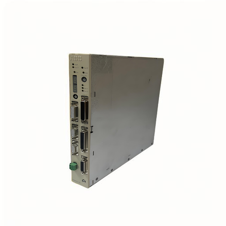
The ABB DI890 3BSC690073R1 is a high-performance enhanced digital input module, whose core positioning is a high-reliability discrete signal acquisition unit for industrial field applications. Adopting an advanced electrical isolation design and a reinforced circuit protection structure, this module enables accurate and stable acquisition and transmission of various digital signals such as dry contacts and wet contacts in the field, providing the control system with real-time and reliable status data of field devices. It is a key core component to ensure the safe and stable operation of complex production processes in industries such as power generation, chemical engineering, metallurgy, and oil & gas.
II. Product Features
Multi-channel Reinforced Isolation Input Design: Integrating 16 independent digital input channels, each channel adopts dual photoelectric isolation technology with an isolation voltage up to 2500V AC. It effectively suppresses ground loop interference, electromagnetic radiation interference and surge interference, completely avoids field signal crosstalk, and ensures the accuracy and stability of signal acquisition. The full isolation design between channels ensures that the failure of a single channel will not affect the normal operation of other channels, greatly improving the fault resistance and fault tolerance of the system.
Wide-range Signal Adaptability: Supporting two signal input types, namely dry contact (passive) and wet contact (active), it is compatible with 24V DC standard industrial power supply signals. It can be directly connected to various field sensors such as limit switches, pressure switches, temperature switches and proximity switches, and is compatible with industrial equipment of different manufacturers and models, greatly improving the flexibility and versatility of system configuration.
Enhanced Diagnostic and Condition Monitoring Functions: Equipped with a built-in high-performance real-time diagnostic unit, it can conduct all-round continuous monitoring of module power supply status, channel signal integrity, line continuity, internal circuit faults, overvoltage/overcurrent status, etc. It supports precise channel-level fault location, and intuitively displays the overall module operating status, power supply status and signal status of each channel (normal, fault, signal valid) through LED indicators. Meanwhile, it can upload detailed fault information to the upper system, facilitating maintenance personnel to quickly locate, analyze and handle faults.
Super Adaptability to Harsh Environments: Using industrial-grade high-stability components and a sealed protection structure, it has an operating temperature range of -40℃ ~ +70℃ and can withstand strong vibration shocks in the frequency range of 10-2000Hz. Its electromagnetic compatibility complies with the highest-level standards of the EN 61000 series, with extremely strong anti-electromagnetic interference capability. It can operate stably in complex industrial environments with dense frequency converters and high-voltage equipment, ensuring that signal acquisition is not interfered.
Flexible System Adaptation and Convenient Maintenance Characteristics: Designed specifically for the ABB AC 800M series controllers, it can seamlessly cooperate with the controller via multiple buses such as PROFIBUS DP, ETHERNET/IP or Modbus TCP. It supports hot-swapping function, allowing module replacement, inspection and maintenance without stopping the system, minimizing production downtime. It adopts a standardized 35mm DIN rail mounting method, which is convenient and efficient for installation and disassembly, reducing the workload of on-site operation and maintenance.
Comprehensive Safety Protection Assurance: Equipped with overvoltage, overcurrent, reverse connection protection and surge suppression functions, it can effectively prevent damage to the module caused by abnormal conditions such as reverse power connection, voltage fluctuation and external surge. It adopts a high-strength engineering plastic shell with a flame retardant rating of UL 94 V-0, which has good impact resistance and corrosion resistance, complying with industrial safety standards. With fast signal acquisition response speed, it ensures rapid capture of field signal changes and guarantees the timeliness and reliability of interlock control.
- Convenient Parameter Configuration and Debugging Functions: Custom configuration of channel parameters, including signal filtering time, diagnostic threshold, signal valid logic, etc., can be realized through the dedicated ABB Control Builder M configuration software. It supports online debugging, parameter modification and program downloading, enabling system debugging and optimization without stopping the machine, simplifying the debugging process. It can be seamlessly connected to the ABB System 800xA monitoring system to achieve remote monitoring of signal status, data trend analysis and fault log query, providing data support for preventive maintenance.
III. Technical Parameters
1. Core Basic Parameters
- Product Model: ABB DI890 3BSC690073R1
- Product Type: Industrial-grade enhanced digital input module
- Manufacturer: ABB Group
- Core Functions: Field digital signal acquisition, signal isolation and conditioning, enhanced fault diagnosis, data transmission and status feedback
- Compatible System: ABB AC 800M series process control system
- Safety Certifications: CE, UL, CSA, ATEX explosion-proof certification, IEC 61010-1
- Input Channels: 16 independent digital input channels with dual photoelectric isolation between channels
- Application Fields: Process control systems, equipment interlock systems, Emergency Shutdown Systems (ESD), Fire and Gas Detection Systems (FGS), and condition monitoring systems in industries such as power generation, chemical engineering, metallurgy, oil & gas, papermaking, water treatment and pharmaceuticals.
2. Electrical Performance Parameters
- Supply Voltage: 24V DC (allowable fluctuation range: 19.2V DC ~ 28.8V DC)
- Input Signal Types: Dry contact (passive), wet contact (active)
- Active Input Voltage Range: 24V DC (typical value)
- Input Current: 3mA ~ 12mA (when the signal is valid)
- Isolation Voltage: 2500V AC between channels and between channels and backplane for 1 minute
- Response Time: ≤ 0.5ms (standard response), configurable filtering time (0.1ms ~ 100ms)
- Insulation Resistance: ≥ 100MΩ (500V DC, between input and ground)
- Surge Protection: ±4kV (differential mode), ±6kV (common mode), complying with IEC 61000-4-5 standard
- Power Consumption: Typical value 4W, maximum value 6W
- Communication Protocols: PROFIBUS DP, ETHERNET/IP, Modbus TCP
- Communication Interfaces: Backplane bus interface, PROFIBUS DP interface (optional), Ethernet interface (optional)
3. Environmental and Physical Parameters
- Operating Temperature: -40℃ ~ +70℃
- Storage Temperature: -40℃ ~ +85℃
- Relative Humidity: 5% ~ 95% RH (non-condensing)
- Vibration Resistance: Frequency 10-500Hz, acceleration 15g (sine wave); frequency 500-2000Hz, acceleration 10g (random wave), complying with IEC 60068-2-6 standard
- Shock Resistance: Peak acceleration 50g, duration 11ms (half-sine wave), complying with IEC 60068-2-27 standard
- Protection Grade: IP20 (complies with IEC 60529 standard, suitable for cabinet installation)
- Shell Material: High-strength engineering plastic, flame retardant rating UL 94 V-0
- Mounting Method: Standard 35mm DIN rail mounting, supporting hot-swapping
- Dimensions: 145mm (width) × 105mm (height) × 215mm (depth) (approximate value)
- Weight: Approximately 0.7kg (including installation accessories)
- Wiring Method: Spring-loaded terminal blocks, supporting 0.5-2.5mm² wire connection with anti-loosening structure
IV. Working Principle
The core working principle of the ABB DI890 3BSC690073R1 digital input module is a closed-loop process of multi-channel signal parallel acquisition - dual isolation and conditioning - enhanced diagnostic verification - high-speed data transmission. Through the coordinated operation of dual photoelectric isolation, signal conditioning, enhanced diagnostic and high-speed transmission circuits, it achieves highly reliable and high-precision acquisition and transmission of field digital signals. The specific working process can be divided into four core stages:
Stage 1: Signal Access and Dual IsolationDigital signals (dry/wet contact signals) from field sensors (such as limit switches, pressure switches and proximity switches) are connected to the module through 16 independent input channels. Each channel is equipped with an independent dual photoelectric isolation circuit, which performs dual electrical isolation between the field input signal and the module's internal circuit and backplane bus. This not only effectively suppresses ground loop interference, electromagnetic radiation interference and surge interference, but also prevents field fault signals from spreading to the module interior and the controller, maximizing the safety and stability of signal acquisition.
Stage 2: Signal Conditioning and ConversionThe isolated signal is transmitted to the high-precision signal conditioning circuit, which filters, amplifies and performs level conversion on the signal, accurately eliminating signal noise caused by electromagnetic interference in the industrial field, and converting non-standard digital signals into standard logic signals processable by the module. Meanwhile, the conditioning circuit real-time monitors the current and voltage status of the input signal to ensure that the signal is within the effective acquisition range, providing a stable and reliable basic signal for subsequent diagnosis and conversion.
Stage 3: Enhanced Diagnostic VerificationThe module's built-in enhanced real-time diagnostic unit adopts multi-dimensional fault monitoring logic to continuously monitor the integrity of each channel's signal, line continuity status, dual isolation circuit working status, power supply voltage stability and internal logic circuit working status. If faults such as channel line open/short circuit, signal over-range, power supply abnormality, and isolation circuit failure are detected, the diagnostic unit immediately generates a detailed fault code, intuitively displays the faulty channel through LED indicators, and real-time transmits fault type, fault occurrence time and other information to the controller. Meanwhile, it verifies the validity of the collected signal to ensure that the signal is not distorted or lost, guaranteeing the reliability of transmitted data.
V. Common Troubleshooting
1. No Signal Input on a Channel, LED Indicator Not Displaying
2. Module Frequently Reports Faults, Multiple Channels Have Abnormal Signals
3. Signal Response Delay, Controller Receives Signals with Lag
4. Module Fails to Communicate with Controller, No Overall Response