Description
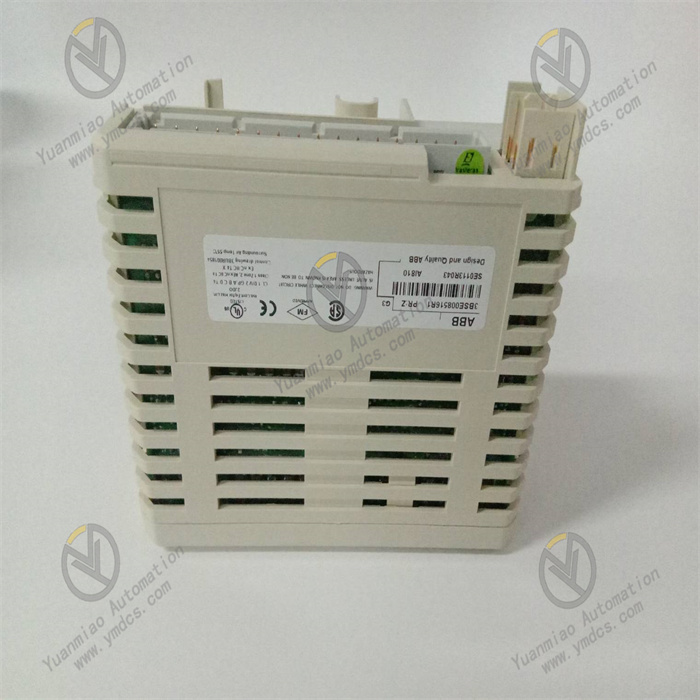
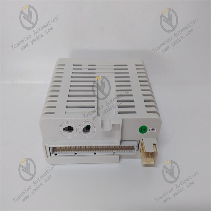
ABB DI820 3BSE008512R1
I. Overview
The ABB DI820 3BSE008512R1 is a digital input module, with its core positioning as a precision acquisition and isolated transmission unit for discrete signals in industrial field applications. Adopting high-performance photoelectric isolation technology, anti-interference signal conditioning circuits and redundant protection design, this module can accurately collect various digital signals on site (such as on/off signals from limit switches, proximity switches, push buttons, relay contacts, etc.). After isolation and conversion, the collected signals are transmitted to the control system, realizing real-time monitoring of key information in industrial production processes, including equipment status, process positions and operation commands. It provides reliable signal acquisition support for automatic control, process interlocking and safety early warning in production processes of industries such as electric power, chemical engineering, metallurgy, papermaking and water treatment.

II. Product Features
Multi-channel Isolated Input Design: It integrates 16 independent digital input channels. Each channel adopts high-performance photoelectric isolation technology with an isolation voltage of up to 2500V AC, which can effectively suppress ground loop interference, electromagnetic radiation interference and on-site high-voltage crosstalk, prevent on-site interference signals from affecting the normal operation of the control system, and ensure the stability and accuracy of input signal acquisition. Full isolation is achieved between channels, so the failure of a single channel will not affect the normal operation of other channels, significantly improving the anti-failure capability and fault tolerance of the system.
- Wide-range Signal Adaptability: It supports multiple digital signal input types including dry contacts and wet contacts, is compatible with the 24V DC standard industrial control power supply, and can match the output signals of various on-site sensors and operating components such as limit switches, proximity switches, photoelectric switches and push button switches. The input signal has a fast response speed, ensuring rapid capture of on-site signal changes and meeting the signal acquisition requirements of high-speed production scenarios.
Comprehensive Diagnosis and Status Monitoring: The built-in real-time diagnosis unit can conduct all-round continuous monitoring of module power supply status, channel input signal integrity, internal isolation circuit faults, overvoltage/overtemperature status, etc. The overall operation status, power supply status and input status of each channel (signal present/signal absent, fault) of the module are intuitively displayed through LED indicators. Meanwhile, fault information can be uploaded to the upper system, facilitating maintenance personnel to quickly locate line faults, sensor faults or internal module faults.
Strong Adaptability to Harsh Environments: Adopting industrial-grade high-stability components and sealed protection structure, it has an operating temperature range of -25℃ ~ +70℃ and can withstand vibration shocks in the frequency range of 10-2000Hz. Its electromagnetic compatibility complies with the EN 61000 series standards, with strong anti-electromagnetic interference capability. It can operate stably in complex industrial environments with dense frequency converters and high-voltage equipment, ensuring that the accuracy of input signal acquisition is not interfered with.
Flexible Adaptation and Convenient Maintenance: Specifically designed for the ABB AC 800M series controllers, it can seamlessly cooperate with the controllers via PROFIBUS DP or ETHERNET/IP bus. It supports hot swapping function, allowing module replacement, inspection and maintenance without stopping the system, which minimizes production downtime. It adopts the standardized 35mm DIN rail mounting method, featuring convenient and efficient installation and disassembly, and reducing the workload of on-site operation and maintenance.
Comprehensive Safety Protection: It is equipped with overvoltage, overtemperature, reverse connection protection and surge suppression functions, which can effectively prevent damage to the module caused by abnormal conditions such as reverse power connection, overvoltage of input signals and external surges. The shell is made of high-strength engineering plastics with a flame retardant rating of UL 94 V-0, having good impact resistance and corrosion resistance, and complying with industrial safety standards. The input circuit is equipped with current-limiting protection function to avoid module damage caused by external line short circuits and ensure system safety.
- Convenient Parameter Configuration and Debugging: Custom configuration of channel parameters including input signal type, response time and diagnosis threshold can be realized through the dedicated ABB Control Builder M configuration software. It supports online debugging, parameter modification and program downloading, enabling system debugging and optimization without stopping the machine, thus simplifying the debugging process. It can be seamlessly connected to the ABB System 800xA monitoring system, realizing remote monitoring of input status, data trend analysis and fault log query, and providing data support for preventive maintenance.
III. Technical Parameters
1. Core Basic Parameters
- Product Model: ABB DI820 3BSE008512R1
- Product Type: Industrial-grade digital input module
- Manufacturer: ABB Group
- Core Functions: On-site digital signal acquisition, isolation conversion, status monitoring, fault diagnosis and data feedback
- Compatible System: ABB AC 800M series process control system
- Safety Certification: CE, UL, CSA, ATEX explosion-proof certification
- Input Channels: 16 independent digital input channels with photoelectric isolation between channels
- Application Fields: Process control systems, equipment interlocking systems, safety control systems and signal acquisition systems in industries such as electric power, chemical engineering, metallurgy, papermaking, water treatment, oil and natural gas, and pharmaceuticals.
2. Electrical Performance Parameters
- Supply Voltage: 24V DC (allowable fluctuation range: 19.2V DC ~ 28.8V DC)
- Input Signal Type: Discrete input (dry contact/wet contact)
- Compatible Sensor Types: Limit switches, proximity switches, photoelectric switches, push button switches, relay contacts, etc.
- Input Voltage Range: 24V DC (typical value), supporting wide-range adaptation of 15V DC ~ 30V DC
- Input Current: Typical value of 3mA ~ 5mA per channel (when powered by 24V DC)
- Isolation Voltage: 2500V AC between channels and between channels and backplane, lasting for 1 minute
- Response Time: ≤1ms (signal rising edge/falling edge), configurable via software (0.1ms ~ 100ms)
- Insulation Resistance: ≥100MΩ (500V DC, between input and ground)
- Surge Protection: ±4kV (differential mode), ±6kV (common mode), complying with IEC 61000-4-5 standard
- Power Consumption: Typical value 3W, maximum value 5W
- Communication Protocols: PROFIBUS DP, ETHERNET/IP
- Communication Interfaces: Backplane bus interface, PROFIBUS DP interface (optional)
3. Environmental and Physical Parameters
- Operating Temperature: -25℃ ~ +70℃
- Storage Temperature: -40℃ ~ +85℃
- Relative Humidity: 5% ~ 95% RH (non-condensing)
- Vibration Resistance: Frequency 10-500Hz, acceleration 12g (sine wave); Frequency 500-2000Hz, acceleration 8g (random wave), complying with IEC 60068-2-6 standard
- Shock Resistance: Peak acceleration 35g, duration 11ms (half-sine wave), complying with IEC 60068-2-27 standard
- Protection Grade: IP20 (complying with IEC 60529 standard, suitable for installation in cabinets)
- Shell Material: High-strength engineering plastic, flame retardant rating UL 94 V-0
- Mounting Method: Standard 35mm DIN rail mounting, supporting hot swapping
- Dimensions: 142mm (width) × 102mm (height) × 212mm (depth) (approximate value)
- Weight: Approximately 0.6kg (including installation accessories)
- Wiring Method: Spring-loaded terminal blocks, supporting 0.5-2.5mm² wire connection with anti-loosening structure
IV. Working Principle
The core working principle of the ABB DI820 3BSE008512R1 digital input module is a closed-loop process of on-site signal acquisition - isolation conversion - signal conditioning - status monitoring and feedback. Through the coordinated operation of photoelectric isolation, signal conditioning, diagnosis monitoring and data transmission circuits, it realizes highly reliable and high-precision acquisition and transmission of on-site digital signals. The specific working process can be divided into four core stages:
Stage 1: On-site Signal AcquisitionThrough 16 independent input channels, the module real-time collects various on-site digital signals, including on/off signals from sensors such as limit switches and proximity switches, as well as status signals from operating components such as push buttons and relay contacts. The input circuit is equipped with current-limiting protection function, which can prevent damage to the internal circuit of the module caused by external line short circuits and ensure the safety of the acquisition process.
Stage 2: Isolation ConversionThe built-in photoelectric isolation circuit of the module electrically isolates the on-site collected signals from the internal circuit of the module and the control system, effectively blocking ground loop interference, electromagnetic radiation interference and on-site high-voltage crosstalk, and avoiding interference signals from affecting the normal operation of the control system. Meanwhile, it converts the non-standard signals input on site into standard logic signals recognizable by the internal circuit of the module, ensuring the stability and accuracy of signal transmission.
Stage 3: Signal Conditioning and TransmissionThe logic signals after isolation and conversion are transmitted to the signal conditioning circuit. The conditioning circuit shapes and filters the signals, removes noise interference in the signals, and improves signal integrity. Subsequently, the conditioned signals are transmitted to the ABB AC 800M controller via the backplane bus or PROFIBUS DP/ETHERNET/IP bus, providing precise on-site data support for the logical operation and control decision-making of the controller.
V. Common Troubleshooting
1. No Signal Input on a Certain Channel, Controller Cannot Recognize On-site Status
2. The Module Frequently Reports Faults, and Inputs of Multiple Channels Are Abnormal
3. Input Signal Response Delay, Status Monitoring Is Not Timely
4. The Module Cannot Communicate with the Controller and Has No Response Overall