Description
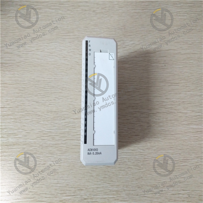
ABB AO810V2 3BSE038415R1
The ABB AO810V2 3BSE038415R1 is an 8-channel analog output module belonging to the I-O module category. As an upgraded version of the AO810 series, it is primarily positioned as a digital-to-analog signal conversion and execution control unit in industrial automation control systems. This module accurately converts digital signals from the controller into standard 0(4)~20mA analog signals. It is equipped with comprehensive self-diagnostic and fault protection functions, and features a compact modular design that requires the use of dedicated module terminal units. It can be seamlessly integrated with automation systems such as ABB System 800xA.
With its excellent control precision, stable operational performance, and flexible integration capabilities, it is widely used in industrial sectors with high control precision requirements, including power generation, chemical engineering, machinery manufacturing, and wind power. It provides stable analog control signals for field devices such as valve actuators, motor drives, and regulators, serving as a key core component to ensure the accurate and efficient operation of industrial production processes.
I. Product Features
1. Multi-channel High-precision Output with Excellent Control Performance
2. Comprehensive Diagnostic Mechanism for Timely and Reliable Fault Warning
3. Multiple Safety Protection Features for High Operational Stability
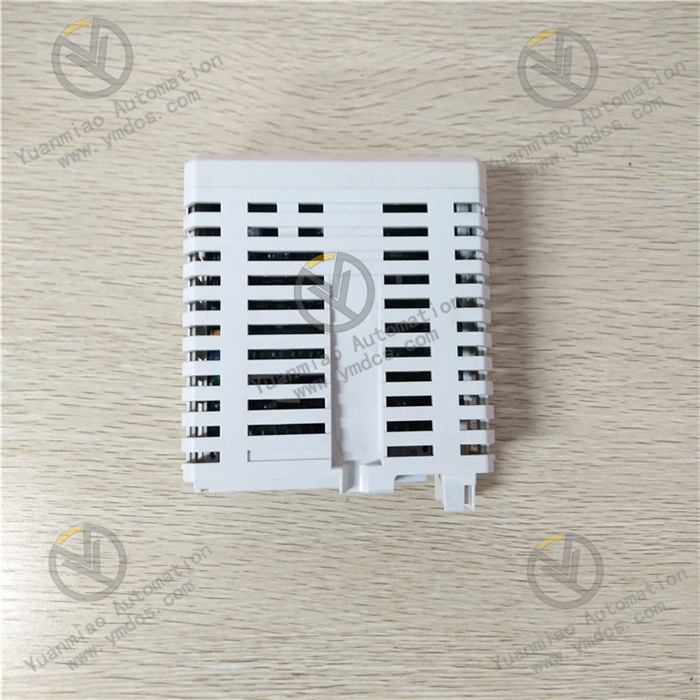
4. Compact Modular Design for Flexible Integration and Adaptation
5. Green Environmental Compliance with Strong Environmental Adaptability
II. Technical Parameters
1. Basic Parameters
- Model: ABB AO810V2 3BSE038415R1
- Product Type: 8-channel unipolar analog output module
- Brand: ABB
- Core Functions: Converts digital signals to 0(4)~20mA analog output; supports self-diagnosis and fault protection
- Replacement Models: 3BSE008522R1, 3BSE038415Z1
- Compatible Systems: ABB System 800xA
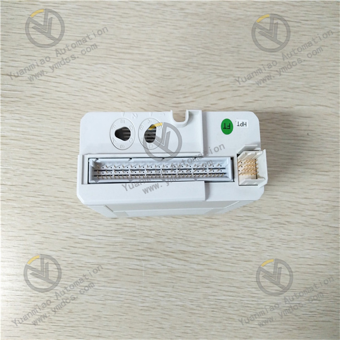
- Compatible Terminal Units: TU810, TU812, TU814, TU830, TU833
- Environmental Compliance: Complies with RoHS Directive (EU Directive 2011/65/EU); WEEE Category 5
- Customs Tariff Code: 85389091
- Net Weight: Approximately 0.19kg
- Gross Volume: 0.546dm³
- Warranty Period: 12 months (original factory standard warranty)
2. Electrical Parameters
- Output Channels: 8 independent channels, unipolar
- Output Signal Type: 0~20mA, 4~20mA (configurable)
- Resolution: 14-bit
- Maximum Load Resistance: 500/850Ω
- Protection Functions: Short-circuit protection (can be short-circuited to ZP or +24V); Output Status on Fault (OSP)
- Power Supply Specification: 24V DC (process power supply)
- Current Consumption: Varies according to configuration
- Diagnostic Functions: Process power supply monitoring; D/A converter communication supervision; Open-circuit diagnosis; Channel fault detection
3. Mechanical and Environmental Parameters
- Dimensions (W×D×H): 45mm × 102mm × 119mm
- Installation Method: Modular installation (used with dedicated terminal units)
- Operating Temperature: Typical industrial ambient temperature range
- Storage Temperature: -40~+70℃ (refer to standards for similar products)
- Relative Humidity: 5%~95% (non-condensing, refer to standards for similar products)
- Protection Class: IP20 (refer to standards for similar products)
III. Working Principle
The core working logic of the ABB AO810V2 3BSE038415R1 analog output module follows the sequence of "Power Supply → System Initialization → Signal Reception and Conversion → Analog Output and Status Monitoring → Fault Diagnosis and Protection". The specific workflow is as follows:
IV. Common Fault Troubleshooting
| Fault Phenomenon | Possible Causes | Troubleshooting and Solutions |
|---|---|---|
| No module response, unable to receive controller commands | Abnormal process power supply; loose or damaged power connection cables; insecure installation or poor contact between the module and terminal unit; mismatched communication protocols between the module and controller; IP address conflict (for networked systems); internal circuit fault of the module | Use a multimeter to measure the voltage of the 24V DC process power supply to confirm the voltage is stable and within the normal range. Check the power connection cables and the connection status between the module and terminal unit, re-plugging and fastening them to ensure good contact. Verify that the communication protocol configuration between the module and controller is consistent; use a network scanning tool to detect IP address conflicts and modify it to a unique valid IP address. If the above checks are normal but there is still no response, an internal circuit fault of the module may be the cause, and it is necessary to contact ABB authorized after-sales service for repair or replacement. |
| Abnormal channel output signal with fault alarm feedback | Open-circuit or poor contact of the output line; incorrect output signal type configuration; field execution equipment load exceeding the module's compatible range (>500/850Ω); excessively low process power supply voltage | Disconnect the module power supply, check the continuity and connection firmness of the output line corresponding to the faulty channel, and repair any open-circuit or poor contact issues. Verify the output signal type (0~20mA/4~20mA) configuration through the system configuration software, reconfiguring and saving it if incorrect. Test the load resistance of the field execution equipment to confirm it is within the 500/850Ω compatible range; if the load exceeds the limit, the execution equipment needs to be repaired or replaced. Test the process power supply voltage to ensure it is stable, avoiding fault alarms triggered by excessively low voltage. |
| Communication interruption between the module and PLC | Mismatched communication protocols (e.g., PLC set to Modbus TCP while the module is configured for PROFINET); IP address conflict or incorrect subnet mask; damaged or poorly connected communication lines | Ensure the communication protocols of the PLC and module are consistent, and uniformly configure communication parameters in configuration software such as Control Builder. Use a network scanning tool to detect IP address conflicts, modify the module's IP address to a unique value, and verify the subnet mask configuration. Check the communication line connection status, troubleshoot any line damage, and replace the communication line and re-fasten the connection if necessary. |
| Large output signal deviation with low control precision | Uncalibrated module output precision; excessive on-site electromagnetic interference; output lines placed too close to power lines resulting in signal interference; unstable load resistance | Re-calibrate the module output precision through the system configuration software or dedicated calibration tools. Check if the module installation location is close to strong interference sources, installing a metal shield if necessary. Re-route the wiring to ensure the distance between analog output lines and power lines is ≥20cm; parallel a 0.1μF/25V capacitor at the signal terminal for filtering if necessary. Test the load resistance of the field execution equipment to confirm it is stable within the compatible range; if the load fluctuates excessively, the equipment needs to be repaired. |
| Frequent triggering of short-circuit protection | Short-circuit hazards in the output line; internal short-circuit of the field execution equipment; incorrect connection of excessively high voltage to the output terminal | Disconnect the module power supply, inspect the output line for insulation damage, line overlap, or other short-circuit issues, and eliminate short-circuit hazards. Test the field execution equipment to determine if there is an internal short-circuit; if so, the equipment needs to be repaired or replaced. Verify the module wiring to ensure no excessively high voltage is incorrectly connected to the output terminal, and re-organize the wiring in strict accordance with the wiring specifications. |