Description
ABB CP676 1SAP576100R0001
I. Product Overview
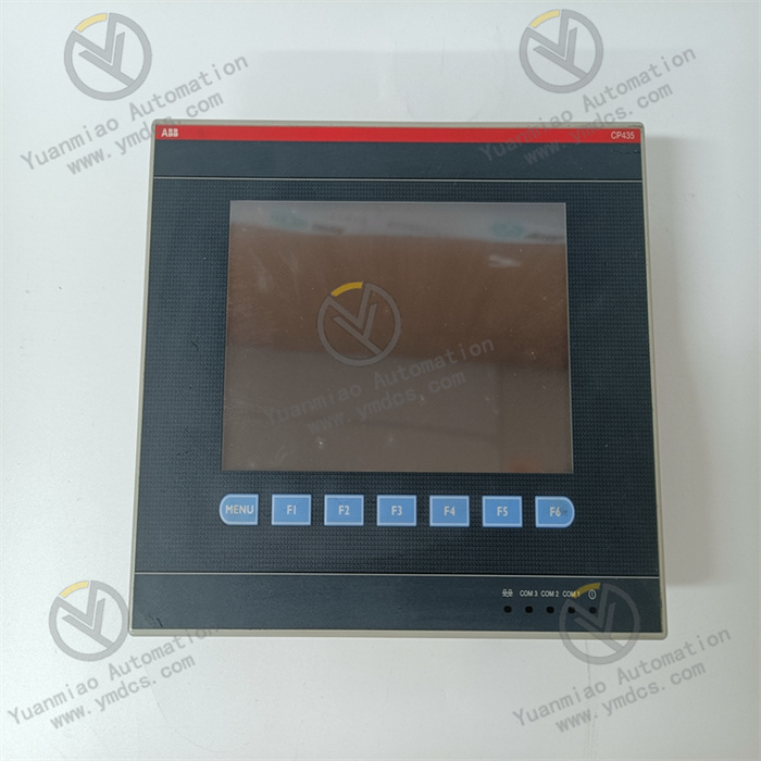
ABB CP676 (1SAP576100R0001) is a touch screen control panel whose core function is to provide a high-definition visual human-machine interface (HMI) for industrial automation systems. It enables core functions such as equipment operation status monitoring, process parameter setting, operation command input, fault information display, and alarm linkage.
As a key interactive hub between operators and the control system, this panel is equipped with the PB 610 runtime license and requires configuration with the dedicated Panel Builder 600 programming software. It can seamlessly interface with ABB AC 500 series PLCs and other industrial control devices that support standard communication protocols.
The product adopts a Germany-originated industrial-grade hardware architecture, featuring a 15-inch TFT color touch screen. It integrates a high protection rating design, rich communication interfaces, and stable operating performance. With a front-panel protection rating of IP66, it can effectively resist dust intrusion and low-pressure water jets in industrial sites, making it suitable for harsh working environments such as dusty and humid conditions.
II. Functional Features
1. High-Definition Visual Touch Interaction for Intuitive and Efficient Operation
2. Rich Communication Interfaces for Versatile System Integration
3. High Protection Rating and Excellent Environmental Adaptability
4. Safe and Reliable Permission Management and Data Storage
5. Flexible Configuration and Convenient Maintenance to Reduce Project Costs
III. Technical Parameters
| Category | Specific Parameters |
|---|---|
| Model/Part Number | Model: CP676; Part Number: 1SAP576100R0001; EAN Code: 4013614493171 |
| Manufacturer | ABB (Country of Origin: Germany) |
| Product Type | Industrial-Grade Color Touch Screen Control Panel (CP600 Series) |
| Core Functions | High-definition visual monitoring, touch operation, parameter setting, fault alarm, 8-level permission management, remote monitoring and control, offline/online simulation |
| Display Parameters | Display Type: 15-inch TFT Color Touch Screen; Aspect Ratio: 4:3; Resolution: 1024×768 Pixels; Color: 64K Colors |
| Storage Parameters | User Program Memory: 256MB; User Data Memory: 256MB; Storage Type: Flash Disk (Non-volatile) |
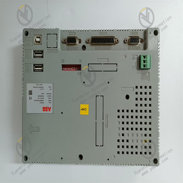
| Communication Parameters | Communication Interfaces: 2×10/100Mbit Ethernet, 1×RS-232/RS-422/RS-485 (switchable), 2×USB 2.0 Host, 1×SD Card Slot, 2×Expansion Slots; Communication Capabilities: Multi-driver Communication, Client-Server Function; Programming Software: Panel Builder 600; Runtime License: PB 610 |
| Power Supply Parameters | Supply Voltage: 24VDC (Typical Value, Compatible with Industrial Standard DC Power Supply); Power Consumption: Compliant with Industrial-Grade Low-Power Design |
| Environmental Adaptability | Operating Temperature: 0~+50℃; Storage Temperature: -20~+70℃; Relative Humidity: 5%-95% (Non-condensing); Protection Rating: Front Panel IP66 (Compliant with IEC 60529 Standard), Housing IP20; Electromagnetic Interference Resistance: Compliant with Relevant Industrial EMC Standards; Mean Time Between Failures (MTBF): 40,000 Hours |
| Physical Parameters | Net Dimension (W×H×D): 392mm×307mm×64mm; Net Weight: 3.3kg; Gross Weight: 4.9kg; Installation Method: Front-Panel Embedded Installation |
| Compatible Systems | ABB AC 500 Series PLCs, Third-Party Industrial Control Devices Supporting Standard Communication Protocols |
| Application Scenarios | Industrial Automation HMI Scenarios such as Oil and Gas, Machinery Manufacturing, Water Treatment, Food and Beverage, Energy Chemical Industry, Automated Production Lines, HVAC, etc. |
IV. Working Principle
The core working logic of ABB CP676 (1SAP576100R0001) is "Configuration Program Driven → Communication Link Establishment → Data Interaction and Transmission → Touch Command Parsing → Information Display and Action Linkage". It needs to cooperate with the upper control system to complete the full-process human-machine interaction function, with the specific process as follows:
Configuration Initialization: Complete user program configuration through the dedicated Panel Builder 600 programming software, including touch interface layout design, process parameter association, communication parameter configuration, permission level division, alarm logic setting, etc. The generated configuration program is downloaded to the panel's built-in Flash Disk memory via USB, SD card, or Ethernet interface. The panel automatically loads the configuration program after startup to complete system initialization.
Communication Link Establishment: Based on the preset communication parameters, the panel establishes a stable two-way communication link with the upper control system (e.g., AC 500 PLC) via Ethernet or serial communication interface. Relying on multi-driver communication capability, it realizes data interaction with multiple control nodes. It also supports client-server mode, allowing it to receive remote control commands and upload local operation data.
Data Interaction and Transmission: Through the established communication link, the panel receives data such as equipment operation status, process parameters, and fault codes uploaded by the control system in real time, while transmitting operators' touch commands (e.g., parameter modification, equipment start-stop) to the control system. It supports offline data storage function, enabling backup of key operation data via SD card for subsequent maintenance analysis.
Touch Command Parsing: When the operator performs an operation via the touch screen, the panel's built-in processing unit parses the configuration function corresponding to the touch signal, generates standardized control commands, and sends them to the upper control system via the communication link to trigger corresponding control actions. For permission-sensitive operations such as critical parameter modification, it automatically triggers an 8-level permission verification process, which can only be completed by authorized users.
- Information Display and Action Linkage: After parsing and processing the data received from the control system, the panel clearly displays it in visual forms such as process flow diagrams, digital dashboards, and parameter curves on the 15-inch touch screen. When fault information is detected, it immediately triggers the alarm linkage mechanism, highlighting the fault code and description information on the screen, and can also link to control on-site audible and visual alarms to remind operators to handle the issue in a timely manner.
V. Operation Guide
1. Installation Steps
Installation Environment
Mechanical Installation
Wiring Operation
2. System Configuration and Debugging
Configuration Programming
Debugging and Verification
3. Operation and Maintenance
Daily Operation
Regular Maintenance
- Weekly: Wipe the touch screen surface and panel housing with a dry and soft cloth to remove dust and stains; avoid using corrosive cleaning agents during cleaning. Check whether the panel is installed firmly and whether the sealing gasket is intact. Observe the display effect of the touch screen to ensure no abnormal phenomena such as screen blooming or freezing.
- Monthly: Connect to the panel through the programming software to back up the current configuration program and user operation data. Check the stability of the power supply voltage to ensure normal power supply. Test the connection stability of each communication interface and verify that there are no abnormalities in the communication parameters. Verify the effectiveness of the permission management function and alarm linkage function. Check the plug-in flexibility of the SD card slot and USB interface.
- Annually: Conduct a comprehensive inspection of the panel by professional personnel to check for aging or oxidation of internal wiring. Verify the touch sensitivity of the touch screen; if there are problems such as inaccurate touch or response delay, handle them in a timely manner. Check the protective sealing performance to ensure that the front-panel IP66 protection rating is not affected. Verify the product certification status; if there is a potential fault risk in the panel, contact ABB after-sales service in a timely manner for repair or replacement.
4. Common Fault Troubleshooting
| Fault Phenomenon | Possible Causes | Troubleshooting Methods |
|---|---|---|
| Panel fails to start with no display | Power supply failure, incorrect power wiring, loose terminals, damaged internal power module | Check whether the supply voltage is standard 24VDC; verify the correctness of the positive and negative pole wiring of the power supply; retighten the power terminal screws; use a multimeter to test the output voltage of the power module; test with a backup power supply; if there is still no response, contact after-sales service to repair the internal power module |
| Abnormal touch screen display (blooming, black screen, color distortion) | Incorrect configuration program, screen surface contamination, damaged backlight module, abnormal ambient light | Re-download the configuration program and test; clean the touch screen surface with a clean soft cloth; adjust the installation position to avoid direct sunlight; if the display is still abnormal, contact after-sales service to test the backlight module and display drive circuit |
| Communication failure, unable to interact with the control system | Incorrect communication parameter configuration, damaged communication cable, loose interface, protocol mismatch, IP address conflict | Recheck the communication protocol, IP address, baud rate and other parameters; check the integrity of the communication cable connection and test with a backup communication cable; retighten the communication interface terminals; troubleshoot network IP address conflicts; confirm that the communication protocol of the panel is consistent with that of the control system |
| Touch screen is unresponsive or imprecise in response | Stains on the screen surface, abnormal touch calibration, incorrect configuration program, damaged touch components | Clean the touch screen surface with a dry soft cloth; re-calibrate the touch via the programming software; verify the correctness of the touch area definition in the configuration program and test by re-downloading the program; if the problem persists, contact after-sales service to repair the touch components |
| Unable to save parameters/data loss | Non-volatile memory failure, incorrect configuration program, sudden power failure, damaged SD card | Check the stability of the power supply to avoid sudden power failure; re-download the configuration program and back it up; replace the SD card to test the data storage function; if the problem persists, contact after-sales service to repair the memory module |
| Abnormal alarm function (no alarm/false alarm) | Incorrect alarm logic configuration, abnormal sensor signal, communication data transmission error, improper permission settings | Verify the alarm logic and parameter threshold settings in the configuration program; check whether the on-site sensor signal is normal; enhance communication anti-interference measures and test data transmission stability; verify the alarm permission settings to ensure that operators have the corresponding viewing permissions |